iCADdocs_online
Retaining Wall Design
The design and analysis of retaining structures and abutment walls is carried out using the RetwallDesign product. It provides a unique and convenient workflow to analyze and document long retaining walls composed of differing section geometry, using widely practiced concepts for the analysis of earth pressure.
The product verifies safety against failure due to overturning, sliding, or heel/toe pressure in excess of allowable bearing capacity. It does not include structural analysis for components. The product offers unique workflow that allows analysis and design of a long retaining wall with different segments, each with separate height and bottom width definition.
Table of Contents
- Conventions:
- Prepare Objects
- Define and Start Session
- ID Segments
- Edit/Review Parameters
- Design Sections
- Saving work
- Presentation and Documentations
- Technical Notes
Conventions:
The following conventions apply to while using the Retaining Wall Design module.
-
Water tables and fill heights are measured from the base of the wall.
-
Section view (unless in Flip Mode) is from left to right facing the beginning of the alignment route.
The workflow for using the module is described below in sequence. {br}
A typical workflow process for the use of this module is shown in the illustration. Each step is described in detail in subsequent sections.
Prepare Objects
The prerequisite objects and their prerequisite is outlined in the Module Browser dialog, while defining the session. Prepare the objects as follows:
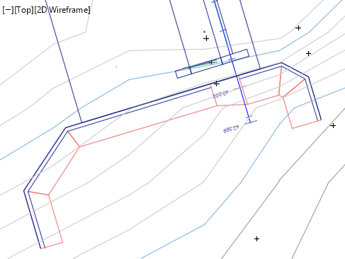
- Draw the layout object following the footprint of the toe of the wall (front face edge) on a plan view area in AutoCAD. Then create a profile data for the Alignment objeect. The profile data creation best serves design and visualization needs if:
- enough offset locations in the transverse directions are included, and
- finer resoltion is available, to allow sufficient incremental representation between segments. (usually 2 to 5m incremtnal interval is recommended).
:bulb: Note: Using curves on alignment objects for retaining walls is will give inaccurate results in plan view and BoQ results. If curves are there, represent using as many vertices as needed.
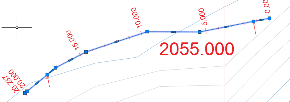
- Prepare wall top and bottom profile objects. This is best prepared from overlaying the profile plot from the layout object, as shown in the illustration.
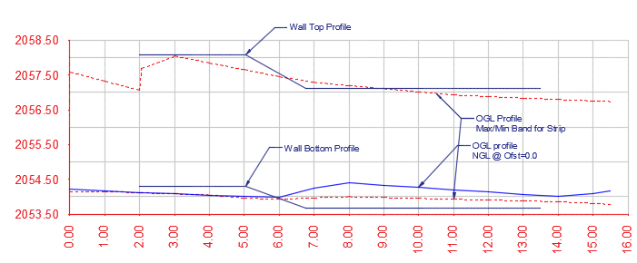
These objects are needed for retaining walls with varying heights along the longitudinal direction. A good example is the abutment wall of diversion weir structures. Otherwise, simple polylines can be used to represent the top and bottom of the retaining wall.
Note: It is important to have sufficient length of equal wall height along the length of the wall. Otherwise, the next step(s) may fail to proceed.
Note: Make sure the wall begins with uniform wall height for a certain distance (5*incremental distance used to generate the profile).
Define and Start Session
To define the design session:
- Clear iCAD workspace from
Workspace > Clear WorkspaceorCTRL+0. - Start the Module Browser from
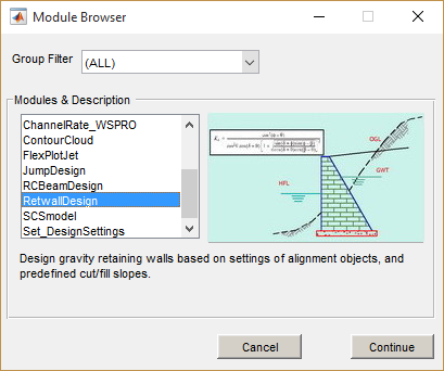
Workspace > Create and Run Sessionor the toolbar item. -
In the Module Browser dialog, select RetwallDesign module.
-
In the New Session dialog, click on the Wall Alignment Object type listed in the left box. AutoCAD will be in select mode. Pick the wall layout object prepared above.
If the selection is accepted, the session is now completely defined. Hit the
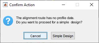
Run Sessionbutton. This will start the elevation view in the main iCAD interface.Note: If the wall alignment object is referenced and does not contain any profile data, simple wall design is possible.Choose Simple Design when prompted. Then provide basie the wall height and foundation depth values. The elevation view is generated for the simple wall. Section view uses a sample profile data.
Provide the dimensions as needed, and proceed.
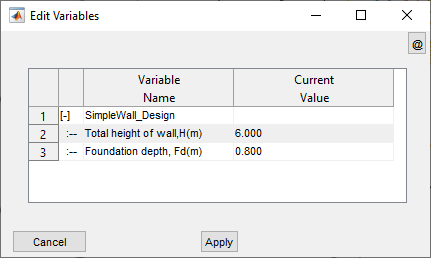
Note an important limitation of simple walls:
- BoQ is extracted for the wall only. No earth volume is included.
- Plan view is not available.
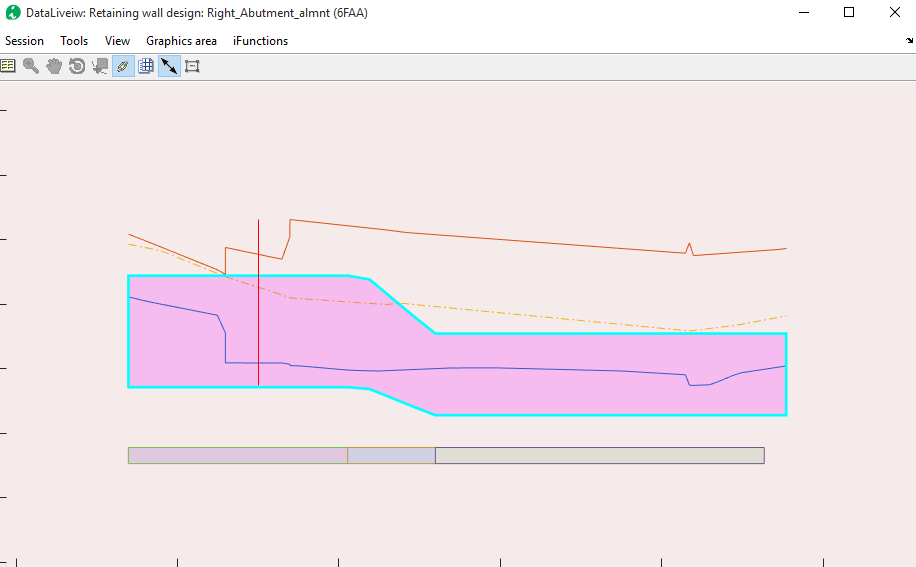
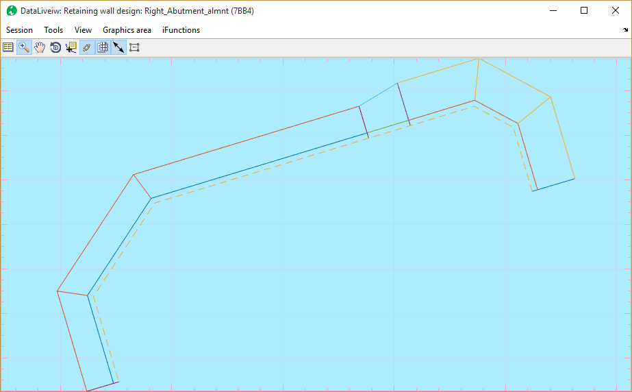
The interface is now to proceed to the next step. If profile data is found, the profile data along the centerline, max and min elevations in transverse direction, as well as the wall face-break points are shown.
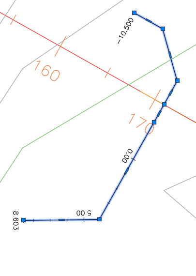
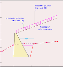
Figure: Plan view of a retaining wall alignment line for a diversion weir structure.
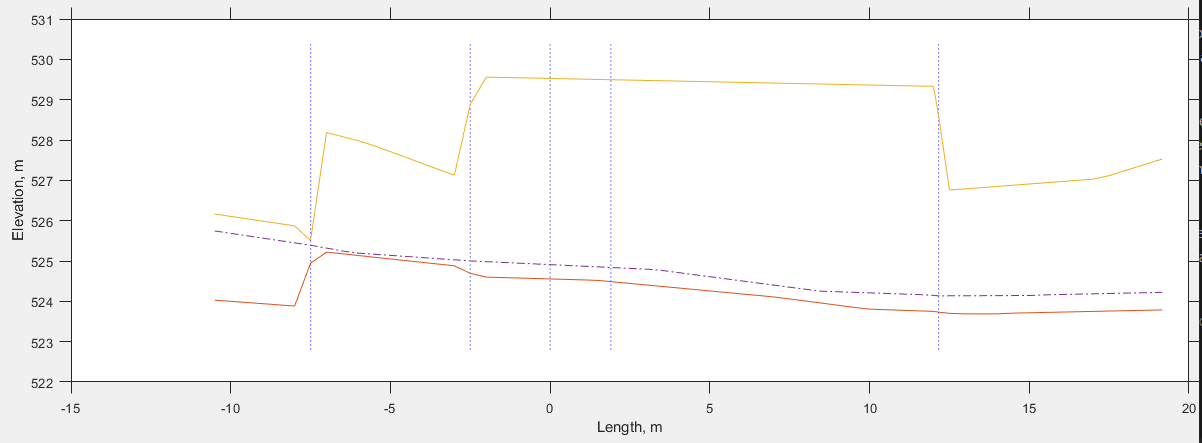
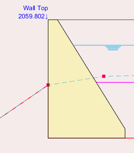
Figure: Starting view of a retaining wall design for complete data, including wall face-break lines
:bulb: Note: In above figure, that the vertices in the alignment drawing in AutoCAD are understood to represent face-break locations along the longitudinal dimensions of the wall.
ID Segments
If the wall face is displayed in the interface, you can skip to the next step below. This is especially true if simple walls are defined. Otherwise, define the top and bottom information from respective AutoCAD objects as follows.
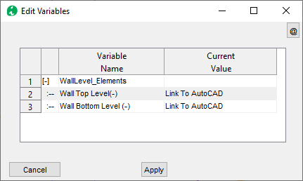
- Go to Workflow > Pick Wall Levels.
- Click on the Wall Top variable value. Go to AutoCAD and pick the object defining the wall top level.
-
Similarly, click on the Wall Bottom Level variable value, and Go to autocad to pick the wall bottom object.
-
Refresh View from Workflow > Refresh View or CTRL+R. The wall face should be visible shaded in the profile view.
-
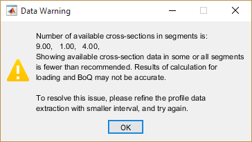
Use Workflow > Id Segments to define the design segments that can be identified from the current setup. When successful, the grouping is displayed schematically at the bottom of the wall with different colors.
Tip: The segments are identified based on the variation of the height of the wall at incremental stations, grouping locations of similar heights together.
Note: At least three incremental stations are expected under each segment group. If this is not met the following flag is thrown. As recommended, quit the design process and extract profile data at finer intervals again.
Edit/Review Parameters
Edit the settings for the different aspects of design and analysis from
-
Edit variables to define Load Elements.
Start the variable editor from Workflow > View Variable Editor. and set each variable to requirement. Below table summarizes input values.
| Group | Variable Name | Description |
|---|---|---|
|
Ground Water Height (m) | Height of water table in the backfill material behind the wall |
| Intermediate Backfill Height (m) | Height of intermediate backfill material | |
| Passive Backfill Height (m) | Height of fill material in front of the wall toe | |
| Drain Water Height (m) | Height of water level in front of the wall toe | |
|
Surcharge Load (KN/m^2) | Uniformly distributed load magnitude |
| Line Load (KN/m) | Line load applied along the length of the all | |
| Point Load (KN) | Point load applied on top of fill material |
Notes: - Load elements heights are measured from bottom of the wall - Loads are applied on top of the backfill material. {br}
Continue.
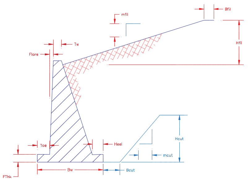
- Edit variables defining the geomery and orientation of the retaining wall section
| Group | Variable Name | Variable description | Remarks |
|---|---|---|---|
|
Top width of wall, Tw(m) | The top width of the abutment wall | |
| T-Shape Dims (m) | [Toe, Stem width, flare, Heel] Wall dimensions specifying the shape and geometry of the wall body including the footing. |
Use [0, 0] for simple gravity wall See notes below this table on how to define different shapes. |
|
| Footing Thickness (m) | Thickness of footing block | ||
| Wall friction angle (Deg) | Wall friction angle denoting the backfill vs back of wall interaction | ||
| Default B/H ratio (-) | Default ratio to determine the bottom width of the retaining wall as a function of the wall height. | This value is used to schematically draw the wall before actual designed width is assigned. Once a design value is assigned, this ratio is not used. | |
| Side Cut slopes, (-)): | [Bcut, mut, hcut] values to specify earth cut slope | See illustration below. Bcut or Bfil: Flat space from cut edge Mcut or mfil: cut slope after flat space Hcut or Hfil: Height of cut |
|
| Backfill Slopes, (-): | [Bfil, mfil, Hfil] values to specify earth fill slope | ||
| Wall face direction, (-) | Wall face direction 1: Orient wall to the left -1: Orient wall to the right |
Direction sect with reference to face looking at end of alignment route. See notes on presentation and documentation section, and the plan view details to learn about the difference. |
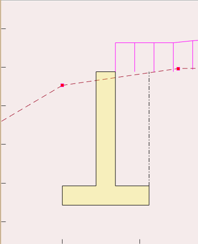
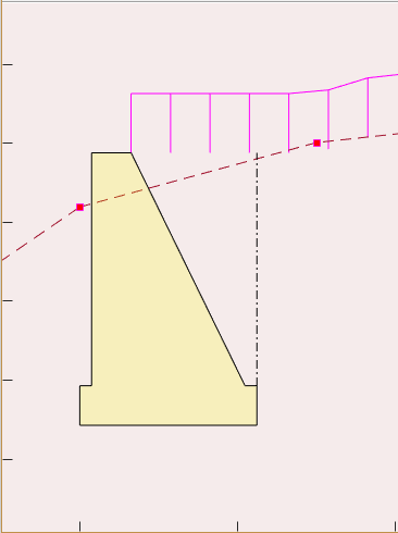
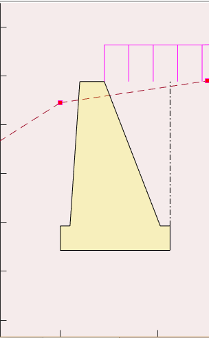
All variables related to Retaining wall described above are schematically outlined in the illustration below.
The following are examples of wall shapes that can be generated. Note: Tw= 0.5m
3. Edit material properties that determine the magnitudes of loads acting on the retaining wall body. A list of common materials are built into the variables and reference values are available as shown in the screenshot next to the table.
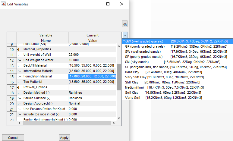
Figure showing backfill material specification, woth build in parameters as a guiding tool.
| Group | Variable Name | Variable Description |
|---|---|---|
|
Unit weight of Wall | Unit weights of the retaining wall material |
| Unit weight of Water | Unit weight of water | |
| Backfill Material | [γ, ϕ, c, γsat] values for earth materials, where: γ is bulk unit weight [KN/m^3] ϕ is angle of friction [deg] c is cohesion [KN/m^2] γsat is saturated unit weight See note below. |
|
| Intermediate Material | ||
| Foundation Material | ||
| Toe Material |
4. Edit and/or set design process related settings and safety parameters for the session.
| Group | Variable Name | Variable Description | Remarks |
|---|---|---|---|
|
Design Method (-) | Design method to be used in analysis: Rankine’s Coulombs |
Apply either Rankine’s or coulombs methods to determine the active and passive earth pressure on the wall |
| Failure Surface (-) | Assumed failure surface for analysis, defining the application point of earth pressures | Rankine’s method assumes a forces are applied on the vertical plane passing through the heel of the wall Coulombs method assumes earth pressures are applied on the back of the wall. |
|
| Design Approach(-) | One of available design options: Nominal DA-1 (Euro Code) DA-2 (Euro Code) |
These approaches establish the load and moment factors to be applied from known practices to determine safety against failure. See technical notes further below for details. |
|
| Use Poisons Ration for Kp at Rest (v) | Poisons ratio value to determine passive pressure at rest condition | See technical notes below for the relationship used. | |
| Include toe side in cut (-) | Include or exclude cut volumes in bill of quantity estimates | ||
| Factor Hydrodynamic Head (-) | Consider or ignore hydrodynamic head in pressure analysis | If ignored, hydrostatic pressures is considered factoring the depth of water at the heel and toe of the retaining wall. | |
| Bottom Width Limits (bwLims) | Whether to limit bottom width dimension input for valid geometry in plan view | If set to None, no limits apply. It can also be set to Alignment Vertices to Automatically set valid limits. | |
| Segment Id Source (-) | Determines how wall segments are identified. It can be set to either of Alignment Vertices or WTBL Vertices. | If available, using the WTL and WBL objects from AutoCAD is strongly recommended. | |
| BoQ Listing (-) | Dictates how BoQ is generated. It can be set to Detailed or Summary | Detailed BoQ lists all items of work for each segment. While Summary option rolls up all quantities of each segment in to individual items of work. |
Most variables will have built in list of parameters, often from referenced litrature, to simplify data input process.
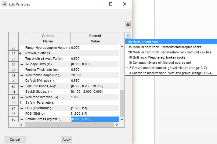 Figure showing options for built in shear stress definition settings
| Group | Variable Name | Variable Description |
|---|---|---|
|
FOS (Overturning) | Desired range of values for factor of safety against overturning. [1.5, Inf] input evaluates safety against minimum of 1.5. |
| FOS (Sliding) | Same but against sliding | |
| Bottom Stress (kg/cm^2) | Allowable bearing capacity of the foundation material [kg/cm^2] |
Note: - Safety parameters are Minimum and Maximum values of parameters with in which range PASS flag is raised. Evaluated safety beyond this range will raise FAIL flag in the analysis report table. - A list of preset materials are available to help choose the right material, or specify a different one.
Design Sections
The next step in the process is to design the actual sections of the retaining structures, factoring safety parameters.
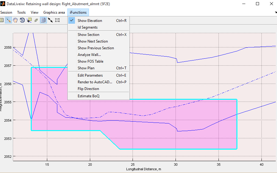
1. Once in elevation view, and variables are set as well as design segments are identified, go to Workflow > Cross Section view or CTRL+X. The interface will be on interactive mode to pick a location for the cross-section view. Click on a region where uniform height exists.
Tip: The location picked is rounded to the nearest incremental station recoded during profile extraction, and the section at that location is generated.
2. Select Workflow > Design Wall… to get a design solution guide on bottom width values that can meet required safety parameters.
The interface shown is displayed with guidelines for picking a design point. In this snapshot, for instance, the Factor of safety for overturning and sliding are met below 1.5meters width. However, the eccentricity safety factor is only met after 2.0meters.
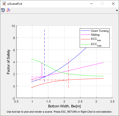
Using the Pick A Scene Solution toolbar, a desired width can be
selected, and the cross-section view will update automatically.
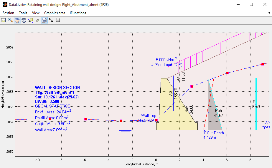
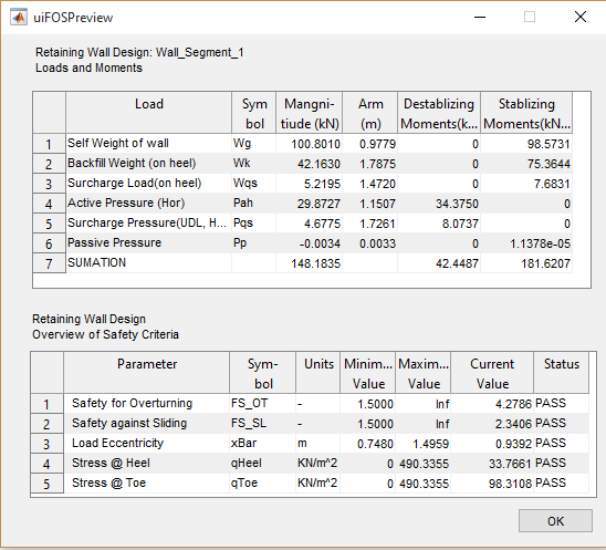
2. Select Workflow > Analyze Wall… menu to analyze the cross-section using current settings. This will generate loading diagrams and summary of safety evaluations against set values.
Tip: Navigate between incremental stations by using
Shift+.(>) orShift+,(<) key.
Ensure all design parameters are met satisfactorily as indicated with the PASS flag at the end of the lower table. If not met, increase or decrease the bottom width as follows:
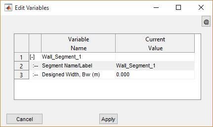
3. Invoke the variable editor for this view from Workflow > View variable Editor or CTRL+E. A compact editor window is displayed, allowing you to edit design segment information.
Note: Segments not designed for bottom width show 0.000 as bottom width value. Once set to a design value, this new value is maintained.
Insert desired value for bottom width and/or segment label and click Apply button.
Note: Transition walls, which are walls with variable height, cannot be directly analyzed. However, bottom widths can be assigned from design results of adjacent uniform height walls. Insert Bottom width for transition walls in pairs, e.g., [2.5, 3.0] implies a uniformly varying bottom width for the wall starting at 2.5m and finishing at 3.0m.
4. Repeat steps 2 and 3 until satisfactory performance is verified against provided safety parameters.
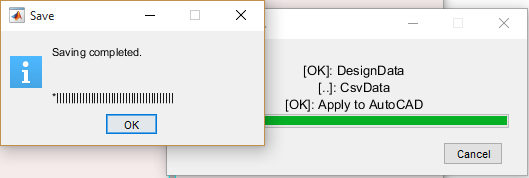
Saving work
Save work from Session> Save menu.
Presentation and Documentations
Once the design is satisfactorily completed for all design segments identified – including transition walls, the finishing solutions can be used to present and/or document the numerous details of the design process. The following are available for this module:
-
Standard output functions for report and BoQ and report generation
-
AutoCAD Drawing for Elevations, cross-sectional and plan layout views
Standard Output Functions
Any of the finishing and presentation solutions integrated in to iCAD workflow can be used with this module. These include:
-
Generating design and analysis report from Sessions > Build Report.
-
Generating bill of quantity (BoQ) estimate from Workflow > Generate BoQ
Note: To generate a complete listing of BoQ, make sure all segments are designed satisfactorily, Navigate cross-section view from beginning to end, and finally, Generate the plan view is also essential.
Generating AutoCAD drawings
Refer to the finishing solutions section of the user manual to learn how common tools are use to generate drawings to AutoCAD, including Transverse and longitudinal cross-section views.
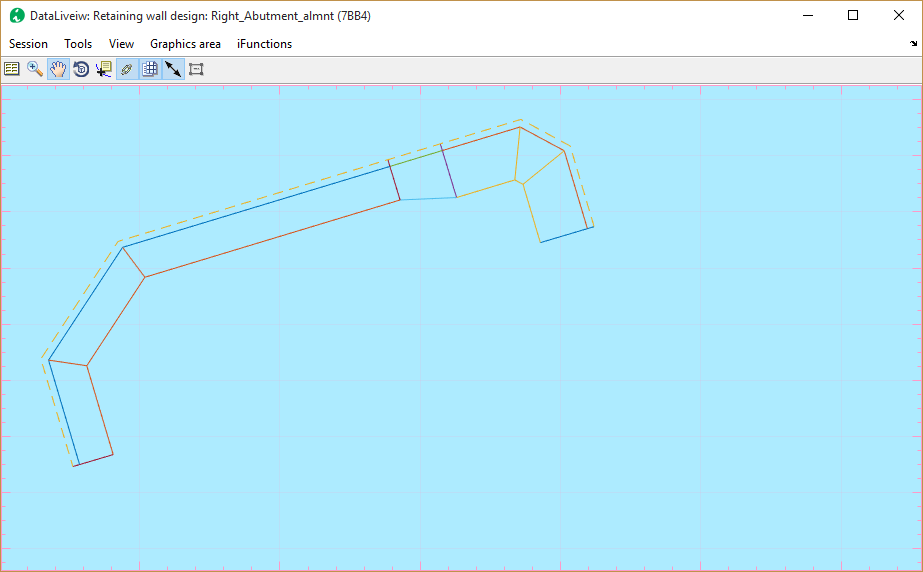
Generating Plan Views
Plan views are key output for this module. These can be used to generate important layout information overlaying topographic maps, as well as related positioning details for the drawing album. To generate the plan view:
1. Make sure all identified segments are designed for appropriate bottom widths. Then go to Workflow > Show Plan or Ctrl+T. The view is generated to maintain the orientation of the layout object.
2. Use the Generating Additional Plots to AutoCAD option to render this to AutoCAD.
Note: The shape of the plan view may be rendered as shown below, if the Wall Face Direction variable under Retwall Settings group is set to -1 (or Right). Use option as fits the context.
Finally, an important guide to ensure smooth design process. The generation of plan view may result in unrepresentative geometry – such as shown below - if the vertices locations on the alignment route and that of the wall top/bottom profile.
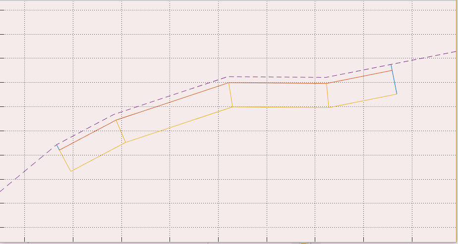
This is common, if the wall top/bottom profile objects are created after the alignment route is set out and the profile is done.
Note: Alignment routes generated from JumpDesign module during the design of weirs are free from such issues.
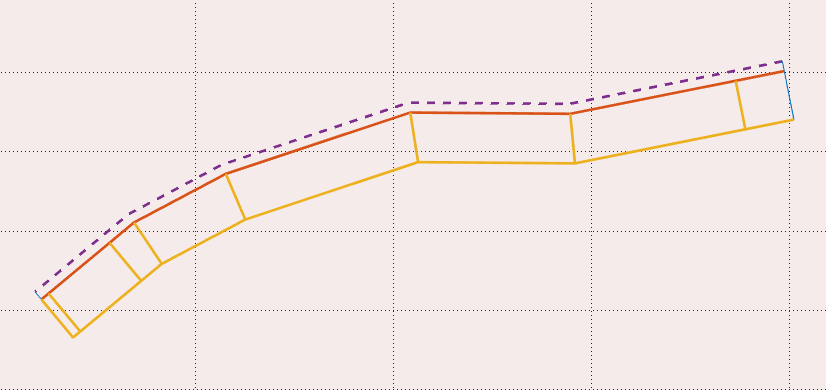
If vertices are in alignment, the correct image should appear as shown here.
To avoid such issues:
1. Draw the layout object overlaying the base map
2. Mark station locations using appropriate intervals (e.g., 0.25, 0.5, 1.0).
3. Decide the beginning, end and interim points for the retaining wall and ensure vertices are created on those locations.
4. Extract the profile with desired offset settings & save the profile data. Before closing the profile data view, use Tools > Copy Graphics (for AutoCAD plot), and use the iCAD menu Tools > Plot to AutoCAD (or CTRL+P) to plot the data to AutoCAD. Use a scale of 1.0 to plot the data.
5. Now draw the wall top level and wall bottom level geometries using the vertex locations positioned in step 2 above.
The design session defined using layout objects and wall top/bottom profiles prepared in this manner will result in expected geometries.
Vertices at 1.25m and 18m stations – same as the begin and end point of the wall top and wall bottom profile objects - as shown give the correct layout.
Note: Wall top and/or bottom profiles need to have the same number of vertices. Profiles provided beyond the start and end of the profile data are trimmed to data range.
:bulb: Tip: A convenient way to ensure proper sync of vertices between the layout object and the eall top/bottom profiles is to align the vertices of the latter to stations that are easy to locate on the layout object. Then the layout object can be edited for new vertices at these locations, and a profile re-extracted.
Walls may not be rendered fully, if WallTop and WallBottom coordinates do not strart at beginning and end of profile data.
Technical Notes
The product identifies segments along the alignment route of the wall. It uses the wall height to identify design ranges with the same wall height dimension, and label them in to segments. Each segment can then be designed separately to determine the bottom width that gives a stable structure.
Earth Pressure Calculation
Earth pressure is computed from the relationship

Where γ is the unit weight of the back fill material, H is the back fill height, and K~a~ and K~p~ are active and passive pressure coefficients, respectively, that depends on the method of analysis.
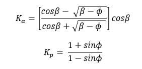
Rankins Concept: Active pressure coefficient in this concept is determined from (Hunt 1986) (Arrora 2004) (Geo5 2005-2017) (W. 1999):
Coulomb’s concept: Active pressure in this concept is determined from
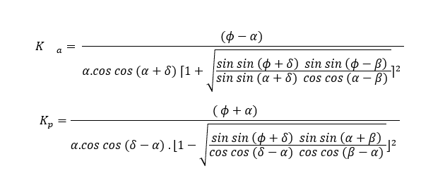
Where φ is the angle of internal friction, α is the back face inclination of structure, δ is the angle of friction between structure and soil, and β is the inclination of backfill to the horizontal.
Note: The coefficients are computed for cohesion-less soil conditions. Also for passive conditions δ = β = 0 condition is assumed.
In the Rankins method, a virtual vertical plane at the heel of the wall is assumed where the earth pressure is acting at an inclination equal to that of the backfill slope.
Normally, in Coulombs method, the forces are assumed to act on the back of the wall, at an angle factoring the soil-structure angle of friction. In Rankine’s method, the failure surface is a virtual vertical plan passing through the heel of the retaining wall. Users can specify failure surfaces as fits their design problem, regardless of the method for computing pressure coefficients.
Pressure Coefficients on Cohesive soils
Coulomb’s theory for cohesive soils estimates coefficient of active earth pressure from:

Corresponding crack location is computed from:

Where γ~t~ is unit weight of backfill material, c~eff~ is the effective cohesion, K~ac~ is the coefficient of pressure due to cohesion, and K~a~ is the coefficient of active earth pressure. In computation, h~o~ can’t exceed the thickness of the topmost layer, or depth to water table in the backfill, whichever is smaller.
Hydrostatic and Hydrodynamic Pressure
Hydrostatic pressure is computed using

Hydrodynamic pressure is computed from the gradient relationship

Where h~w~ is the difference in water is surface elevation, d~d~ and d~u~ are the depth of the water table at heel and toe side respectively.

Where γ~sat~ is the saturated unit weight of the earth body.
Pressure from external loads
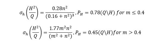
Pressure distribution from uniformly distributed, line or point loads on the grade line of the back fill is estimated from the following relationships.
Uniformly distributed loads:

Where q~s~ is the load [KN-m-2], K~0~ is the coefficient of active earth pressure.
Line loads:
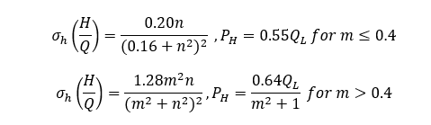
Where n and m are distance factors.
Point Loads:
Where the European code of practice applies, the design approach is set by the user to available options. The following load factors apply respectively.
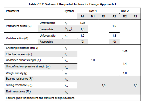
Accordingly, vertical and horizontal components of active pressure are calculated.
Table: Values of partial factors in Design Approach 1 (DA1-1, DA1-2) (Adrew J. Bond 2013)
Stability Analysis
Stability against acting loads is verified using five parameter test, namely Factor of safety against overturning, Factor of safety against sliding, load eccentricity, stress at toe and heel of the wall. The relationships that are used to verify stability are summarized below.
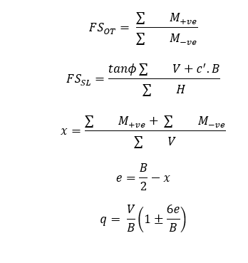
Where ∑M~-ve~ is summation of negative or destabilizing moments, ∑ M~+ve~ is summation of positive or stabilizing moments, ∑V is summation of vertical forces, B is Bottom width of wall, e is eccentricity, c’ is cohesion of foundation soil, and q is the stress at the bottom of the wall (heel and toe respectively).
Geometric Limitations
The RetwallDesign module can model most wall shapes including T or cantilever walls, semi-gravity and gravity walls, subject to the following limitations:
-
The module solves horizontal bottom
-
Unguided use of the module, without adequate technical support, for Wall sizes greater than 7 meters is not recommended.
-
The solution may abort with unhandled error if calculated cut profiles do not intersect NGL. This may happen for large bottom width dimensions.
END.