iCADdocs_online
Introduction to iCAD Software
This page gives an overall introduction to the software, its application and use. Use the ToC below to navigate through this page. Click on Back to Home above to navigate back to the home page.
Table of Contents
Introduction
iCAD software is one of the products, along with CanalNETWORK, iRoads and others, available from our company (Quanomic Engineering Services). It is one of the earliest products we have launched in early 2020.
The software is developed to provide fit-for-purpose solution that is tailor made the sepecific challenges of developing, implementing and operating water resourced development projects. It is known that commercial software and design tools that can handle the design of infrastructure in the water resources secgtor are rarely available. As a result the conventional practice is forced to use inappropriate tools that are old, heavily manual, and impossible to customize. Construction and operation performance of projects is poor, and we believe design is the main source of fault.
iCAD software brings design tools that are built on the latest computational algorithms and technology accessible, with the ease of an interactive graphical user interface, as well as the ability to seamlessly communicate with AutoCAD environemnt. We built on specific use cases and requirements of the practicing engineers, to make sure the solutions are a good fit to the needs in the industry.
To achieve these, we partner and collaborate with key stakeholders in the industry, academia and end users. Visit our website to lear more.
iCAD software components
The iCAD software starts with this interface as the main applicatoin component.
 {br}
{br}
- Product version and Tier show the version of the current application, and its tier. There are three tiers available Standard, Professional, or Enterprise. The different tiers offer differing levels of funcitonalities.
- Session toolbar: These toolbar items give quick access to functions used to manage the iCAD workspace, and the data and sessions there in.
- View toolbar: These toolbar items allow to change and adjust the current view of the main interface to suit differing display requirements. For instance scaling, axis visibility, zoom and pan, and Data tips.
- JetModules Toolbar: Jet modules are modules with in iCAD software that can be invoked with out the need for AutoCAD objects (as data source or host.) They can be quickly invoked from this toolbar part. Examples inlcude, creating and editing plot axis in AutoCAD, Marking alignments, Surface data inquiry, multi-label plots, etc.
iCAD is a modular appliacation software. There are over 20 modules defined and avialable in the current version of iCAD. The user can pick and use any of these modules by associating the right AutoCAD objects. Modules defined as such are called sessions of the module. When a session is run, the iCAD main interface is populated with relevant graphic contents, as well as menu items.
- A module can be defined for multiple sessions. Eg., Retaining wall module can be defined in two sessions, one for left wall and one for right wall.
- There can be any number of modules defined only one module can be run at a time.
Modules and their Application
The current version of iCAD application software include the following modules.
Data processing Modules
- Axes: Prepare, edit and refine plot axes in AutoCAD, used to present plot data. Edits annotation of horizontal and vertical axes elements
- chartViewB: Digitally read charts with accuracy using interactive tools; charts can have both linear and logarithmic axes. Inline interpolation is possible.
- cadExtrract: extract and export geometric properties of CAD objects, including area, perimeter, coordinates.
- Plot Data: Plot any given text/table data to AutoCAD environment. Allows quick and accurate presentation of data in to AutoCAD envirinment.
- Mark Alignment: Create and edit station markers for alignents, with flexible specification.
- inquire3d: Interactive 3D data inquiry over a surface data (or spot cloud data). The tool can also do grade search and determine a path of constant grade along the surface.
- FlexPlot: plotting function to generate all sorts of graphic to AutoCAD environment, from axes, to data plots, to contours, to shop-drawings.
- MultiLabelPlot: used to generate axes and formation level information using common presentation style (such as used in Civil 3D)
The above modules are called Jet Modules. They do not require AutoCAD objects to start, but may operate on AutoCAD objects in process.
Sessions using Jet modules can be run while an other module is running. They do not need to be saved.
Design Modules
The other group of modules are sandard modules, that are defined using specific AutoCAD objects that are expected to contain some data. These modules are described belos.
- ContourCloud: Takes a spot data list, typically from a surveying work, and uses it to generate surface model, and then develop contour maps. Users can delineate regions and corridors automatically, or manually. Contours can be generated with desired spacings, and can be rendered to AutoCAD environment with labeling information.
- ALignmentProfileJET: generates a 3D profile data (strip profile data) along a given alignment line, and allows to take cross-section at any point along the alignment. It stores the data for use by other modules (e.g., Diversion Weir design, Terraform, …)
- ChannelRating_WSPRO: takes a cross-section data of a stream or river, and user defined hydraulic parameters like bed slope, to determine the stage-vs-discharge relation ship at that cross-section. Multiple sections, the most recommended methods, can be easily structured and analyzed to get a better estimate. The results are saved on the cross-section object for use by Diversion Weir Design module.
- Diversion Weir Design: Takes a weir axis with a profile data, and a rated river cross-section, to position, analyze and design the placement of a diversion weir structure. It is capable of overflow, subsurface flow, and sluice bay flow analysis; it can size and design weir body, abitment walls, downstream appron, and cutoff depths. It can model trapezoidal or ogee shaped weirs.
- TerraForm module uses an alignment object with a profile data, and user defined assembly information for earth works, to accurately determine cut/fill volume works involved. It can accomodate parameteric cut and fill shapes, and combine assemblies to create complex earth work definition. It can generate sections, and plans. The module can be used to calculate volume estimates for emabnkment/earth dams, dykes, bunds, ponds, and similar structures. 1.SCS model A hydrologic peak flood estimation model, that automates process used by the SCS method. Profile data along the main stream line, and Curve Number values are used as input. The user can experiment quickly with diffenent user defined values such as AMC (Antecedent Moisture Content), Tc (Time of concentration formulae), Duration and the like. The module produces the expected peak flood hydrograph.
- RetwallDesign: Takes an alignment path with a profile data from AutoCAD, and uses user input values to determine the geometry of the desired retaining wall. It then analyzes and designs the wall using either the Rankines or Culomb’s theory of earth pressure. It can account for hydrostatic and hydrodynamic pressure, and allow modelling up to three different layers of back fill materials. The European code of standard is availble.
:exclamation: Note: Available functionality in your installed application differs depending on the subscription of choice for the product tier, i.e., Standard, Pro, or Enterprise.
AutoCAD addons
iCAD software comes with a bridge application that operates from with in AutoCAD environment. This application is loaded in to the start-up suit of AutoCAD (see installation guideline.)
iCAD application always attempts to launch this bridge application with the current and open AutoCAD drawing file. When succesful, they are displayed on the left side of AutoCAD drawing area by default, with the name iCAD Addon Tools (Ver x.x).
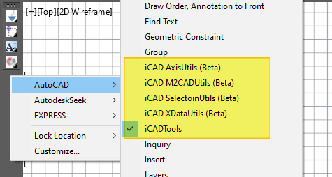
Right-click on the toolbar displays currently loaded Addon tool along with others in the AutoCAD system.
There are four tool sets. Each toolbar button expands, corresponds to a group of associated toolsets, and can expand to show all.
- To expand the buttons, click and hold. Do NOT release the click to navigate to the toolbar needed.
- Hover on a button while holding the click to see tool tips.
iCAD Axis Utils
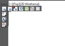
These contain tools used for working with axes pairs, and objects referenced to them. The buttons, in their order of appearance in below figure, are used to
- geneerate data tips on referenced objects
- match text height properties
- Generate contour labels on contour plots generated by iCAD (contourCloud module)
- Refence objects to a pair of axes, and
-
generate grids for a pair of axes.
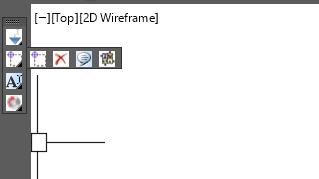
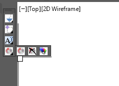
iCAD Selection Utils These toolsets contain utilities that are used to create and work with object selection in AutoCAD. The buttons, in their order of appearance in figure below, are used to:
- Create, and populate, the collection set for iCAD application.
- Clear the collection set for iCAD application
- Instance a collection of objects
-
Toggle PICKSTYLE autocad system variable to enable or diable group selection.
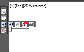
iCAD XData Utils
Users may need to tag objects in order to work with iCAD. This is achieved using the buttons in this toolset. They allow to:
- Attach Tag to AutoCAD objects
- Annotate Object Tag to the drawing
-
Create Aligned annotation from Tag objects.
M2CAD Utils
The buttons in this toolset are used to work with drawing data generated by iCAD. They can:
- render drawing information (left in memory)
- clear drawing information (left in memory)
-
use random colors to generate drawing information (in memory).
Visibility of toolbar
The iCADTools toolbar can be managed in two ways:
- right-click on the toolbar, click on
AutoCAD >context menu, and check/uncheckiCADTOols. This will show or hide the tool bar. - start
-TOOLBARon the command line of AutoCAD, and type in iCADTools, then type in Show, Hide as needed.
:bulb: Note: While using the first method to hide the visibility, the toolbar container is hidden. Hence the context menu is no more accessible. Use method to in this case.
END.