CanalNetworkDocs_online
Design of Regulating Structures
Flow regulating strucrures are a key component of a canal network system. They are provided at different points along canal routes to provide adequate control of flow condition during conveyance of irrigation water to different parts of the irrigation area.
CanalNETWROKcurrently allow the design of Head Regulator Strucures and Cross-Regulator Strucrture. The design of these structures is handled with in the CanalNETWORK environment. Follow below links to navigate this page.
- Defining the Structure
- Design Settings for HR/CR structures
- Designing the Canal Structure
- Exploring Solutions
- Technical Notes
Defining the Structure
The design of regulating and conveyance structures is carried out using floating nodes. Floating nodes can be used for many purposes. Representing a structure is only one of the uses (Refer the chapter on Longitudinal Design for more details.

Important Notes Before defining and designing structues with in the CanalNETWORK environemnt, it is recommended to understand the following notes:
-
Floating node positions can be created ONLY at stations in profile data, and hence are restrained by profile data available, and minSpacing project preference setting. It is important to consider this during profile extraction.
- CR can be placed on any canal, any segment.
-
HR requires a regular (junction) node - connecting to a parent canal - just upstream of its location that is labeled neither as Turn Out nor as Division Box.
- No drop strucrutes are allowed between the upstream node, and the floating node representing the structure.
To insert the floating node along a canal route:
-
Select the route in layout view.
-
In profile view select a segment in the route where you would like to locate the structre.
-
Go to
Workflow > Floating Nodes > Insert New. This will activate an interactive tool to pick a location with in the segment selected. Pick a location.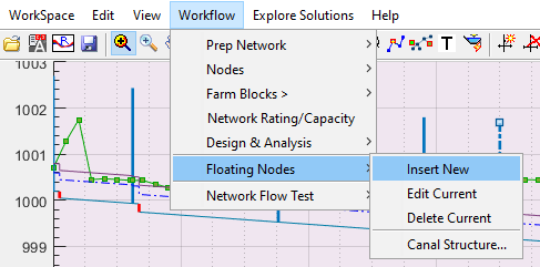
Insert New menu command.
You can also edit the location after insertion by using
Workflow > Floating Node > Edit Current, by first selecting the node.You can also delete floating nodes from
Workflow > Floating Node > Delete Current, by first selecting the node. -
Click on the floating node just inserted to select it, and go to
Workflow > FLoating Node > Canal Structures...to define the strucrure. The Edit Variables dialog box appears for user input. Supply data as below:
-
User Tag or Name: specify the name of the individual structure that can adequately identify the structure properly latter. A standard convention is to use the canal route tag and type of structure, if needed including a serial number. (eg., HR 01 TC_3_12). This input is used to identify the control structure on plan views annotations.
-
Type of Structure: The type of structure the floating node represents. Select from the available list (select the proposed structure of interest either cross regulator, head regulator or inclined drop).
Cross Regulators: structures that are located on parent canals at a position some distance downstream of an off-taking branch canal. They are used to regulate head of flow in the parent canal, so that required amount of water flows to the branch canal. Often, their crest level is set the same as the canal bed level), Head regulators.
Head Regulators are structures posited on branch canals. They usually have their crest levels raised in proportion to the expected overflow discharge rate.
-
Next Action: The proposed action to execute upon hitting
ApplyButton. There are two options.Save saves the information provided on the floating node objects, and exits.
Design This choice saves the data, and continues to the design process. Note, if there is an existing design information on the selected node, the option will appear as Redesign.
- Hit the
Applybutton to continue.
Design Settings for HR/CR structures
Specific parameters and settings for regulator structures design is found as part of the proejct preferences setting. It can be accessed from Workspace > Edit Preferences... menu command. The parameters are shown below.
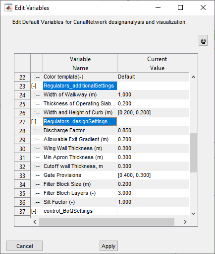
Each of the variables are used in design, drawing generation and BoQ estimation as needed in different workflows. The following table defines and explains each variable.
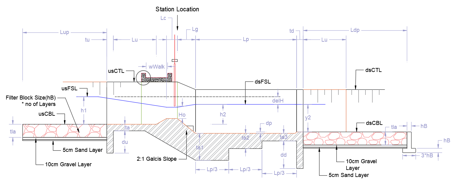
Some of the paramters are shown also in the below typical section figure.

Design Settings
| No | Variable Name, and Unit | Values | Remarks |
|---|---|---|---|
| 1 | Discharge Factor | min 0.5 max 1.0 Default: 0.85 |
A discharge reduction factor to represent minimum flow conditions. Note: This is applicable in CR structures only. |
| 2 | Allowable Exit Gradient(m) | min: 0.10 max:0.3 Default:0.2 |
Desired safe exit gradient desired at downstream end of the structures. This value is used to determine the depth of the downstream cutoff wall and the overall length of the impervious floor of the structures |
| 3 | Wing Wall Thickness(m) | min: 0.20m max:0.50 Default:0.30m |
Desired thickness for all wall components of the structures. |
| 4 | Min Apron Thickness(m) | min: 0.20m max:0.50 Default:0.30m |
Apron thickness for upstream and downstream impervious floor. Note, for downstream floor, apron thickness is also calculated based on subsurface flow conditions and resulting unbalanced head. The applied thickness is the maximum of the two. |
| 5 | Cutoff Wall Thickness(m) | min:0.05m max:0.50m Default:0.30 |
Thickness values for cutoff walls or piles as needed. |
| 6 | Gate Provisions | Gate width: <ul>min:0.30m max:1.0m</ul>Pier Width:<ul>min:0.15m max:0.50m |
Gate provision, specified as a pair of values representing GATE WIDTH, PIER WIDTH. |
| 7 | Filter Block Size(m) | min:0.20 max:0.50 Default:0.20 |
Desired filter block sizes to be used for design. Note, these are applied also considering the number of layers (below) |
| 8 | Filter Block Layers(-) | min:1 max:3 Default:3 |
Specifies how the filter blocks are laid out for quantity estimation. Note: A desired arragnement can be created by manipulating the block size and number of layers. |
| 9 | Silt Factor | min:0.05 max:12.5 Default:1.0 |
Silt factor for use in scour depth estimation and subsequent sizing of upstream and downstream cutoff walls, as well as sizing of the launching appron thickness. |
Additional Settings
| No | Variable Name, and Unit | Values | Remarks |
|---|---|---|---|
| 1 | Width of Walkway(m) | min:0.6m max:1.5m Default:1.0 |
Clear walkway desired on the operating slab or bridge deck of the structure, exluding the curbs on both sides. |
| 2 | Thickness of Operating Slab(m) | min:0.10m max:0.30m Default:0.20m |
Thickness of the concrete slab. |
| 3 | Width and Height of the Curb(m) | min:0.10 max:0.3 Default:0.20 |
Thickness and height of the side curbs on the operating slab.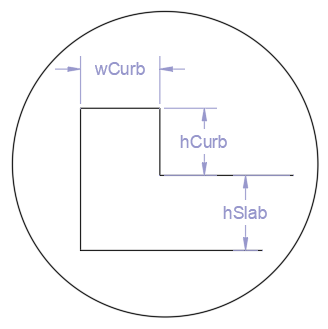 |
Designing the Canal Structure
The design of a structre represented with a floating node can be started or revisited at any time by following these steps.
- Click on the floating node, and start the menu command
Workflow > Floating Nodes > Canal Structure.... - On the Next Actions variable of the edit dialog, choose
DesignorRedesignoption, and hitApply.
This will proceed to the design process.
Important Note: The design settings on project preferences are used in all design/redesin tasks. It is recommended to set these values once, and retain for the life of the project design.
In below sections, detailed presentation is made regarding the design steps followed for each structure.
Design of Cross Regulator Structures
Technical details on theoretical basis implemented in the software is included below in Technical Notes.
Cross-regulators are designed with out overflow crest height, or h~c~=0.0. The software searches for an ideal drop height that meets modular flow requirements.
The search begins from the currently provided drop height with increments of 2.5Cms until an acceptable flow condition is found. The detail view axis shows the solution found.
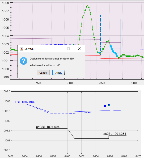
Note: The solid line represents Normal flow volume, and dotted lines represent the reduced flow volume.
If solution fails, the following message is thrown.
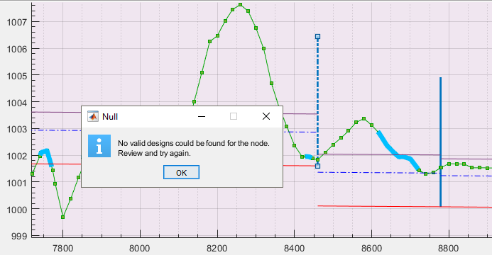
Note: It is recommended to start design with no exit drop provided. However, setting a desired height is also acceptable.
Design of Head Regulator Structures
Detailed theoretical basis for the design of regulating structures is included further below under the section Technical Notes.
For succesful design of head regulator structures, the floating node representing the structre must meet the following requirements.
-
The canal alignment mut be a branch canal to a supply canal. HR structures can not be applied on a parent canal for the project.
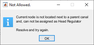
-
The upstream node on the parent canal can not be a division box or a turnout.
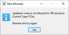
-
The node must be the first structure in the canal (no drops or other node/controls) before its location.
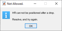
-
The available bottom width must be greater than or equal to the gate width specified in the project preferences.
Once these conditions are met the floating node is accepted for design as a head regulator structure. The process is much similar to that explained in Design of Cross Regulator Structures above.
The following workflow is implemented.
Note: We refer to the supply canal as the parent canal. The Host canal is the canal on which the head regulator structure is located.
-
Determine the upstream flow condition, based on the hydraulics in the parent canal as well as the host canal alignment. This considers both the normal Q and factored Q**Q~minFac~ flow rates in the parent canal. See Technical Notes below for details.

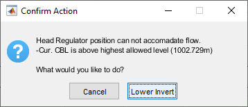
This step often requires repositioning of the starting invert level for the host canal, inorder to accomodate the flow within the design full-supply-depth. Confirm to the prompt, and the invert level is adjusted. Click on the route in plan view to see the changes.
-
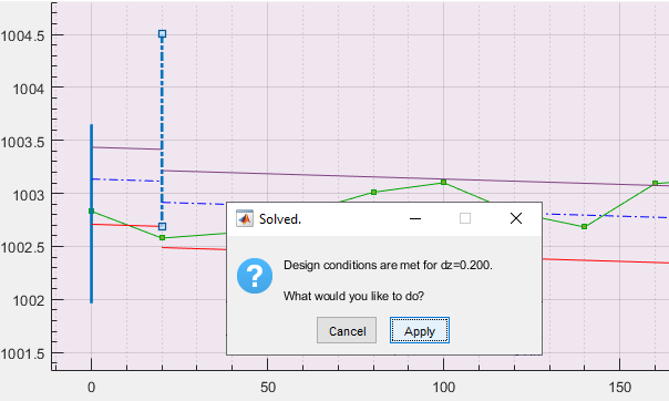
The design of crest height and fall heigh is then carried out by considering modular flow requirements and broad crested weir flow conditions. A dialog confirms the solution, and graphical presentation shown in the detail view axis.
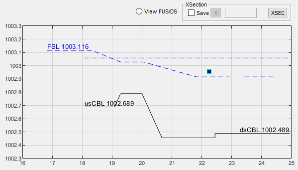
Different solutions for the design can be explored as detailed in the following section.
Design of Inclined Drop Structures
Introduced Dec,2024.
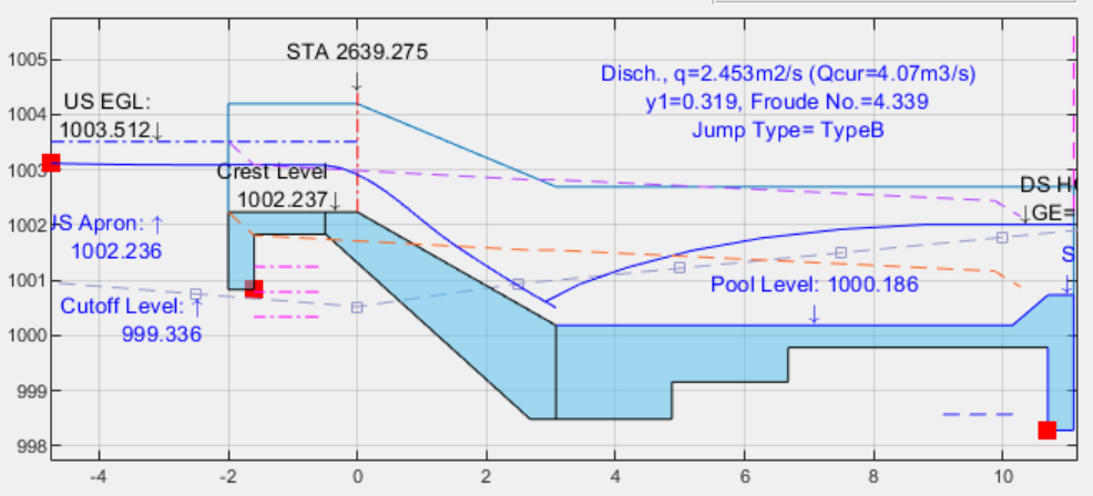
The design of inclined drops is handles by use of floating nodes, like many other structures in irrigation systems. This include Head and cross regulator structures. The properties and various settings are managed from the floating node, once the node is defined as a structure.
Assumptions
The following are the key assumptions and limitations of the current release.
-
The chute length is hydraulically short. This means, there is no enough length in the glacis for significant head loss to affect the pre-jump flow depth. If this condition is not met, the designed energy desssipation pool will be conservative.
-
The canal section upstream and downstream of the drop location are identical in all respects (roughness, side slope, bed slope, discharge, etc…)
-
Thickness of various components at Thk= 0.40;
-
No Transvverse variation og ground level is considered.
The following features will be included in upcoming versions.
- Quantity estimation
- Type III and Type IV energy dessipators
Design Procedure
After the floating node is defined as an inclined drop Type, the design is automatically carries out. There are two specific design tasks as follows:
-
Notch Width: The first step is to determine a notch width required at entry to the drop, in order to mainatin the water surface elevation in the incoming canal.
This is determined by solving the following known conditions at entry to the drop.
yn= 1.5Yc — (1)
yc= (q^2^/9.801)^(1/3)^
Note: If notch width below 0.40m results, the design will not continue.
-
Stilling Pool depth The stilling pool is desinged in such a way that depressed floor provision can sufficiently reduce sequent jump depth to be less than or equal to the existing tail water depth.
yn+dht+dFloor= y1+v1^2^/2/9.801) — (1)
y2= y1/2 + (sqrt(1+8F^2)-1) —- (2)
Note: If depressed flood depth exceeds 1.0m, the design will not resume. This is typically applicable in Type I jump mechanism provissions.
Exploring Solutions
One can explore solutions for Head and Cross-regualator structures as follows.
Dimension Tables
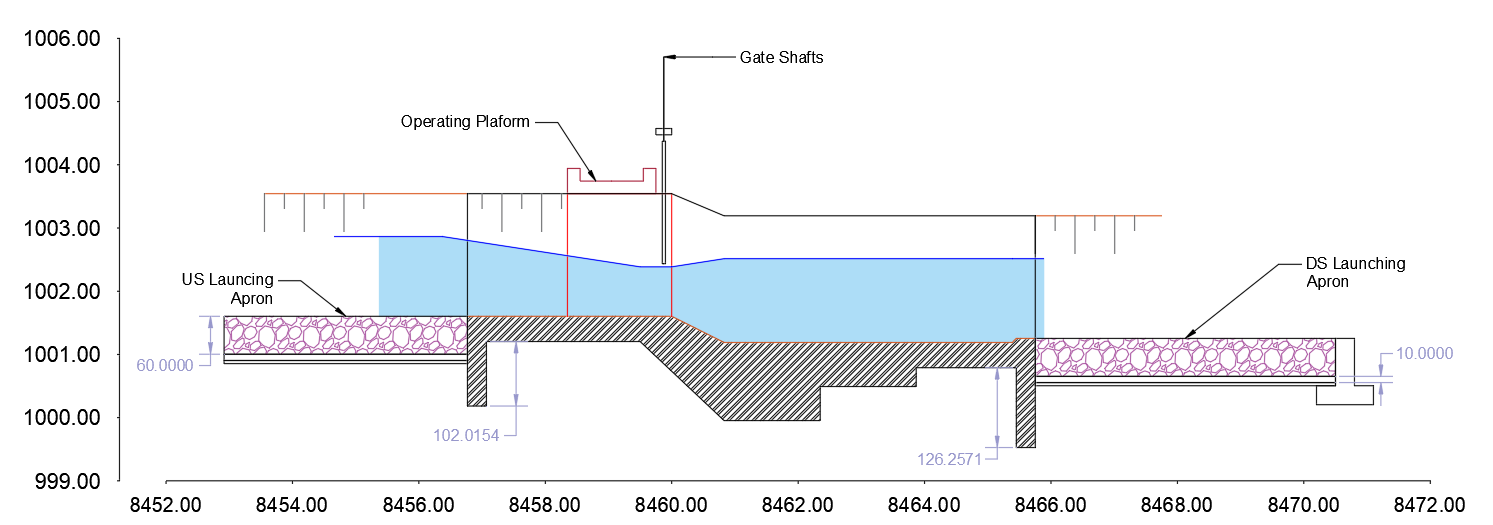
To list the dimension table for structures, follow below steps. The dimension tables are generated in accordance with the symbols and drawing presented below.
- Make sure there is no selection in profile view.
-
Then start the menu command
Workflow > Floating Nodes > Canal Structures.... This will start the below dialog box.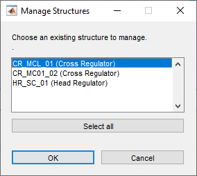
-
To delete or see the summary data related to a single structure skip to next step. To create the dimension tables, select desired structures and hit
OKbutton.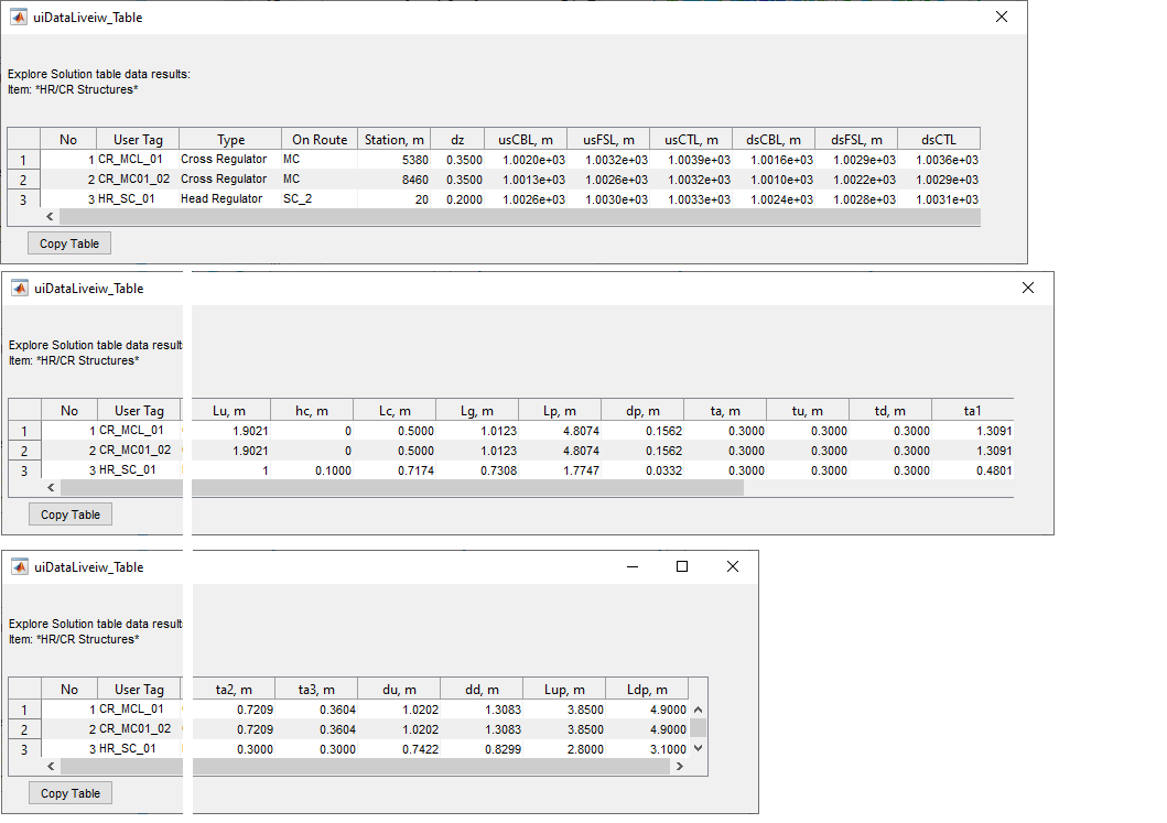
-
choose one of the structures, and hit
OKbutton. Confirm your desired action.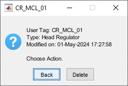
Detailed Drawing Views
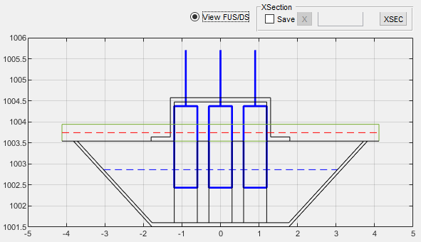
For a floating nodes whose design is fully solved and completed, section and elevation views can be generated. To view these,
-
Select a desired node on the profile view axis.
-
Toggle the View FUS/FDS radio button above the detail view axis to generate alternate views. When toogled on an elevation view is generate.
-
When toggled off, a longitudinal section is created.
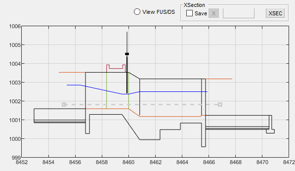
These drawings can be sent to AutoCAD at a desired scale and annotated for more detailed presentation.
Bill-of-Quantity
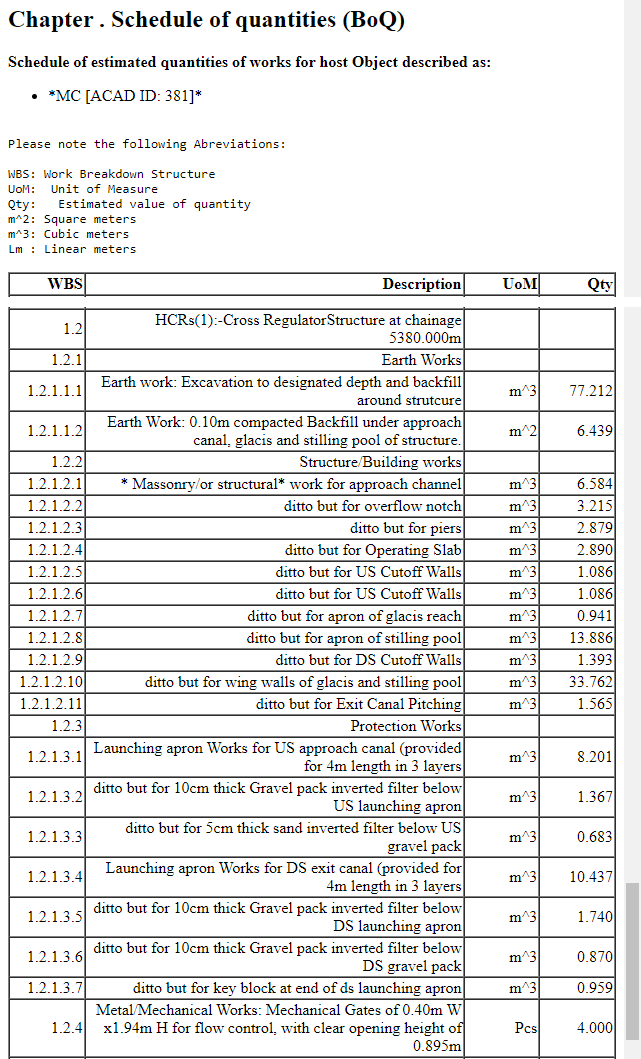
Bill of quantity is included as part of the canal route quantity schedule. To create one:
-
Select the desired canal route containing the structure, and make sure profile data is generated using
Workflow > Data Tables > Lsec Profile Data.... -
Use
Workflow > Data Tables > Generate Route BoQ...menu command to create the BoQ schedule.Tip: You can select the structure node, and create a specific BoQ for the node (and the segment upstream).
Technical Notes
The design of cross-regulator and head regulator structures is carried based on the following considerations:
Note: Crest heihgts for overflow section are set automatically as follows.
- For Cross-regulator structures, hc is set to 0.0, retaining the CBL (Canal Bed Level) upstrem of the node locaiton.
-
For head regulators, hc is set to a minimum value of 0.05m.
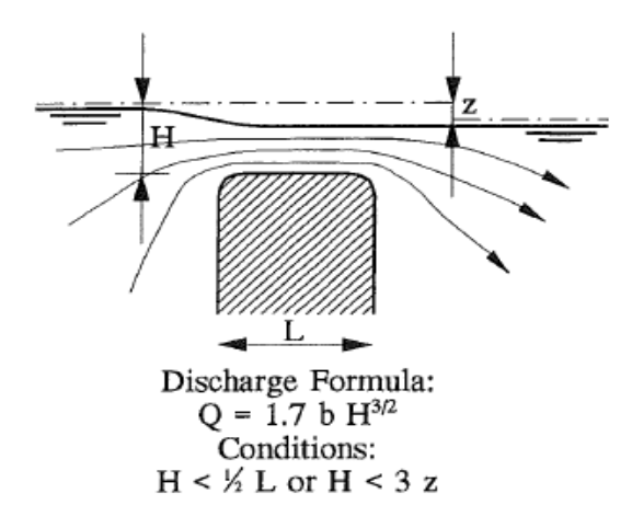
  Q = C_dBH^{3/2}
  Where:
  C~d~ is the Coeficient of discharge
  B is the available overflow length
  H is the resulting overflow head above crest level
The design of regulating structures is carried out ALWAYS to attain modular flow over broad crestd weir. Hence Cd value 1.70 is used.
Overflow Width Design: The design process attempts to optimize available canal bottom width and set gate provission specifications to determine a feasible combination of gates and piers for the overflow section. This process also attempts to maintain the overflow head to closely match the existing normal flow depth in the incoming canal.
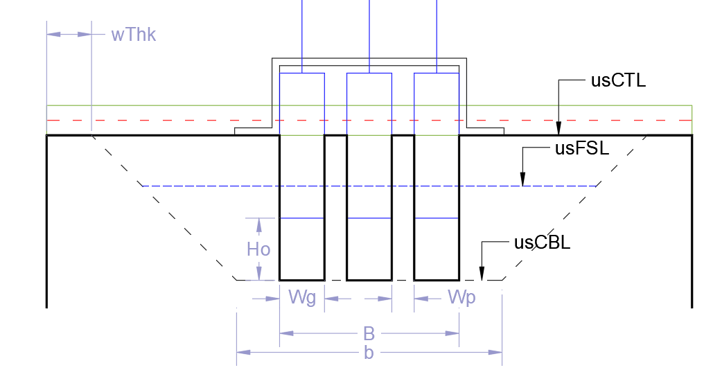
Modular Flow The design iteration is carried out until a modular flow condition is ensured based on the following relation ship (See section figure above).
\[h~2~/h~1~<=0.75\]Note: Modularity is checked and established for both the normal (Q) and reduced (Q*Q~minFac~)discharge rates passing through the regulating structure.
For head regultors, the overflow condition is matched with upstream hydraulics at the parent canal (both normal and factored flow rates.)
The following schematic shows considerations built in to the software for upstream flow hydraulics on a head regulator structure.

Note: the software considers normal flow and minimum flow rates in the parent canal, and the crest height is designed for the minimum flow conditions antiticpated in the parent canal, while attempting to maintain modular flow for both flow conditions in parent canal.
The above two considerations set the allowable headloss for the structure to operate optimally. Pre and post jump depths, y~1~ and y~2~ are then determined from energy conservation equations
Length of stilling pool is determined from
L~pool~= 5(y~2~-y~1~)
the length of the glacis is determined using glacis slope m~glacis~, crest height h~c~, depth of pool d~p~ and the elevation difference between the entry and exit to the structure as follows:
L~glacis~= m~glacis~*(h~c~+HL+d~p~)
The length of the overflow crest is determined to ensure broad crested weir flow using:
L~crest~= 2*h~1~, Lc>=0.50m
The overall length of the impervious floor is determined from khoslas set of relations.
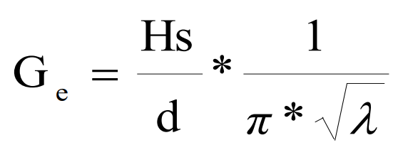
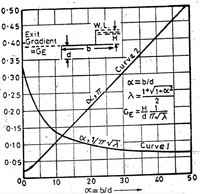
The above relations allow determination of a safe overall length for the impervious floor. This in turn allows sizing of the upstream apron as follows:
Lu= L~total~-(L~glacis~+L~pool~), L~u~>=1.0m
Once the overall sizing of the structue is finished, protection works are sized as follows.
R= 1.35(q^2^/f)^1/3^, if h~1~<4.75q^1/2^, or
R= 0.473*(Q/f)^1/3^, otherwise.
the, upstream and downstream cutoff depths (du, dd) are estimated from:
du= 1.25R-y~1~, and
dd= 1.5R-y~1~, dd>=d~Gexit~
Note: m~galcis~=2.0 for all calcualtions.
END.