CanalNetworkDocs_online
Construction Tools
Begining Jun 2023, we have introduced solutions that can assist during supervision works. CanalNETWORK product has significant potential to contribute to construction processes and drive efficiency. Its data models and computational algorithms offer a strong platform to deal with routine bottlenecks encountered during construction supervision. The following are currently available.
:exclamation: Important Note: This tool may not be available on your application depending on the version you are using, and your subscription level. Contact us for any querries.
Table of Contents
- Generating Shop drawings
- Changing Profile data for Canal Routes
- Alternate canal routes
- Estimating progress
Generating Shop drawings
Use the guides in the Design Prodduction document of this guide, to generate the following working drawings to construction teams:
-
Canal cross-sections at increments
-
Extended cross-sections at desired stations
-
LSec Details for a specific range of station
-
Exagerated plans between stations
-
Extended Plans between stations
-
Canal Junctions and structures
Changing Profile data for Canal Routes
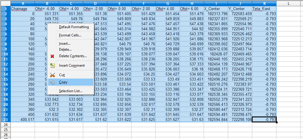
Often times, topographic data on the ground is different from that used during design. In such instances, revising design of canal routes can be done easily. To succesfully make the review, the data of the new topography for the canal route in question must be available in below format.
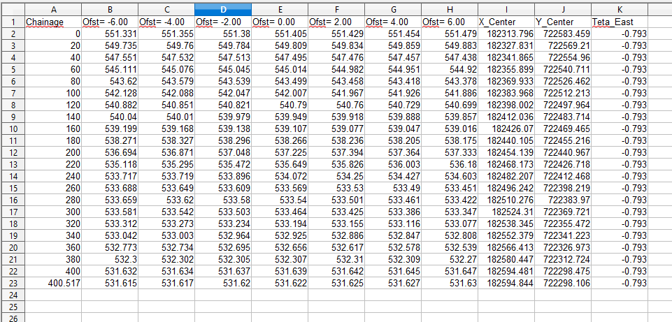
Note: This action will replace all ground reference information for the canal, and the shape of the route can change in the plan view as well.
Make sure:
-
data contains all necessary columns for longitudinal referenceing (chainage),
-
Only one Ofst=0.0 is available to show centerline OGL
-
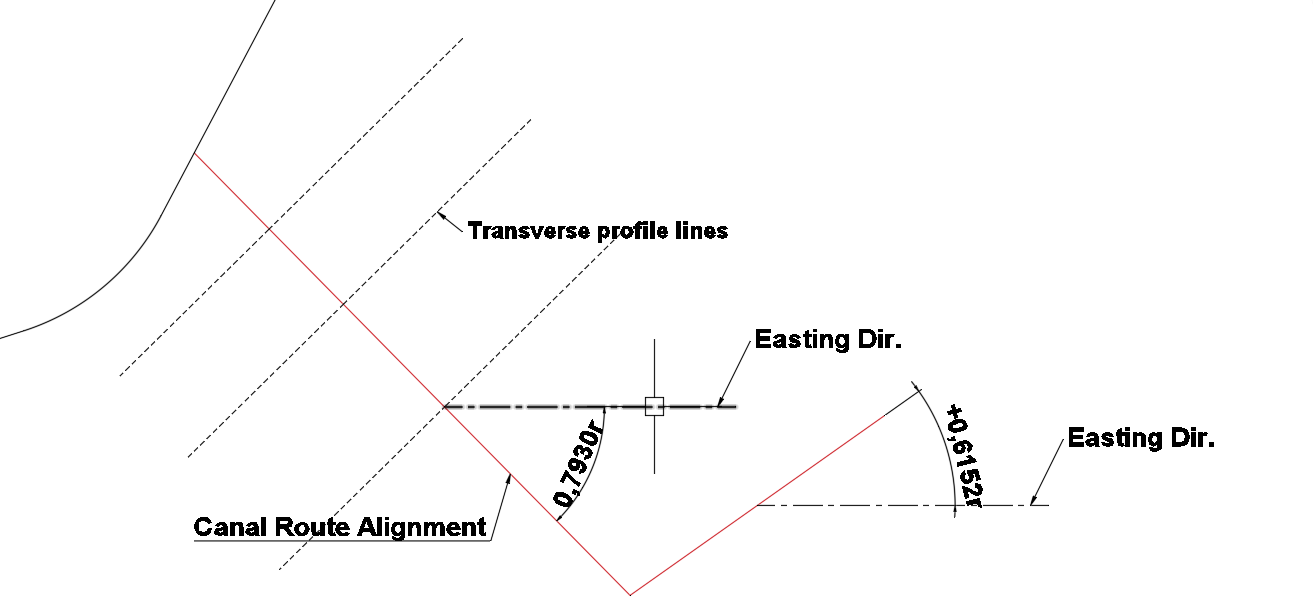
X_Center, Y_Center and Teta_East columns, are available and contain valid data. X_Center and Y_Center represent Northing and Easting along the centerline of the profile data. Teta_East represents the bearing of the front leg at the given station (along the centerline) with respect to the East.
-
At non straight routes, all the vertices of the alignment route must be captured for best results.
-
The Teta_East values are averaged at each station to smooth out drawing generation.
To replace the design data with such data collected from the field follow the below steps.
-
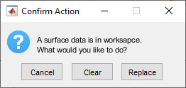
In CanalNETOWRK, make sure there is no surface data on the workspace - i.e., if the
Load Hosted Data...menu item is not checked. If it checked, click on it, and chooseClear.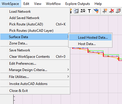
-
Ensure that you are using the right source. If the project uses Alternative File as a source, link that file from
Workspace > File Utilities > Alternate Csv Data Source.... If not, i.e., if using the same source file as the buddy file, leave as is. -
Finally, Check the final station on the profile data matches (closely) with the length of the route measured on AutoCAD. If this is an issue, the process will not compelte.
Now, Copy the data in the table to the windows clipboard (Ctrl+C), being careful not to include empty cells or unwanted colmns or rows.
-
slect the route object you want to apply the new data, and start the menu command
Work Flow > Routes > Route Profile.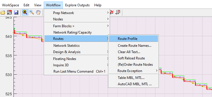
-
A dialog will apear confirming there is no surface data on workspace. Choose
Paste CSV.Note: It may help to copy the table data, just before choosing
Paste CSV. -
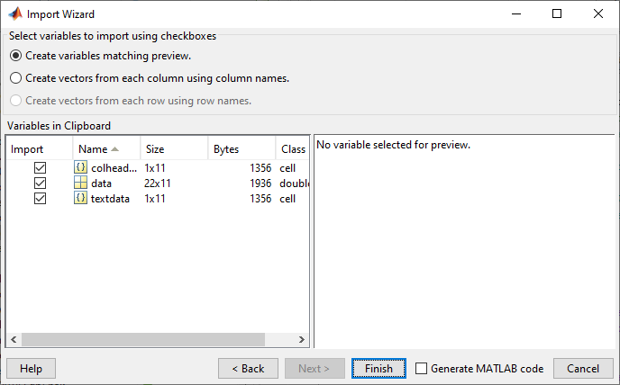
Choose
NextandFinishon the import wizard to complete data import.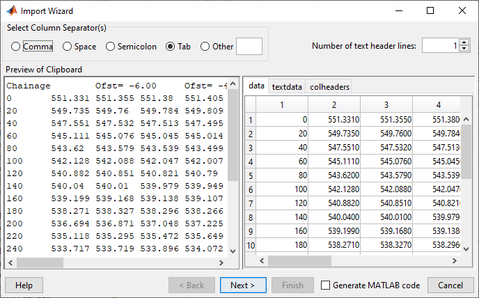
If there is an issue, a dialog such as below will appear.
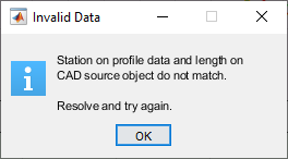 Otherwise a confirmation dialog appears. Hit
 Applyand you are done.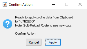 .
.
To see the the newly applied profile data, use Workflow > Routes > Soft Reload Route menu command.
New drawings and volume calculations and design reviews are now possible with the new data.
Alternate canal routes
[To be included soon]
Estimating progress
This tool can estimate the volume of earth works executed under cut and fill conditions for a desired reach in a canal route. Surveying data collected along the canal centerline (representing modified Bed Level or MBedL) and along the canal top level (representing modified Top Level or MTopL) are required. The calculation of volumes are made up on the following assumptions:
-
Elevation values on surveying data represent a flat surface to the left and right of the station they represent
-
Executed fill work at a given station is calculated up to MTopL level on both left and right side banks. The assumption is the center - i.e., the water way is finished to design level as well. MBedL has no effect at stations fully in fill.
-
Missing data at begining or ends are set to ground levels (OGL) in design data.
-
Missing survering MTopL= in a given range, the methods assumes the following:
Two sources for survey data can be used.
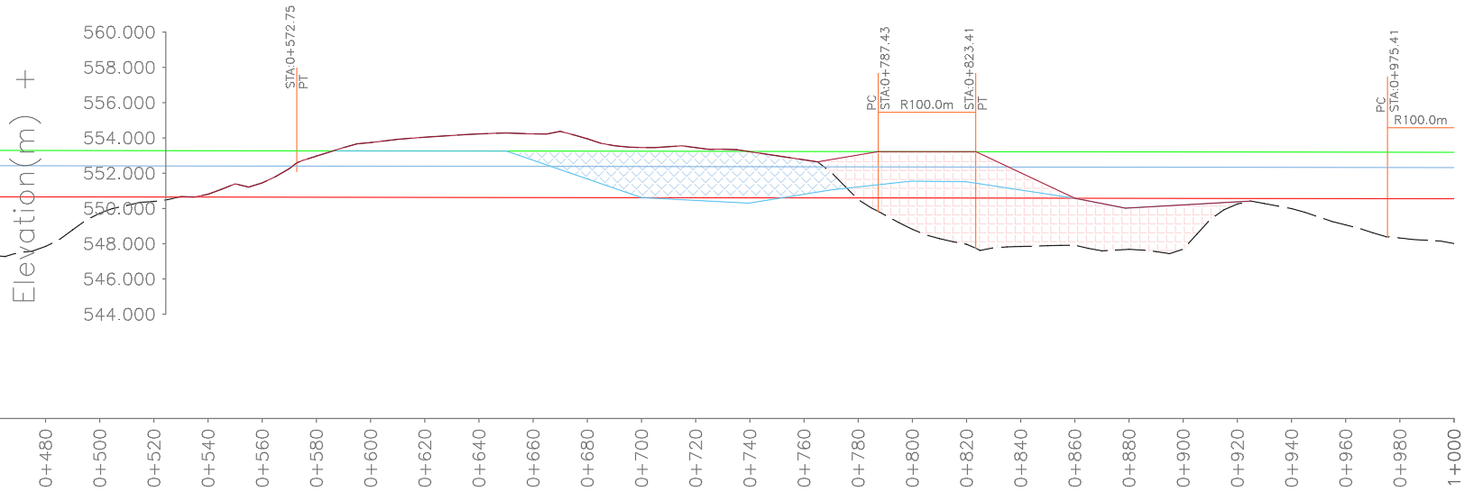
Method1: AutoCAD drawings
Use Profile drawings on AutoCAD created to scale. These must be referenced (using iCAD Addon tools) to the corresponding axes, or it will not work. For best results, draw survey data on existing profile drawing for a given route, before using it.
Method 2: Table data
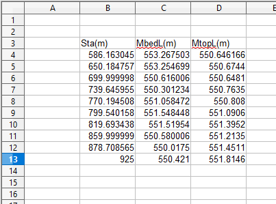
Use table data presented in a spreadsheet (such as MS Excel). The table data can be three column data containing STA, MBedL, MTopL. It can also be four columns containing STA, MBedL, STA, MTopL.
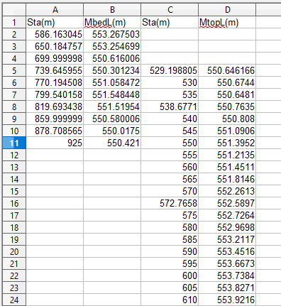
To analyze work progress, surveyed progress data must be avilable in the current workspace of CanalNETWORK. To begin, click on the canal route to meausre to make the profile view available. Then:
-
Start Routes > AutoCAD MBL, MTL menu command. AutoCAD will be on select mode and will prompt you to pick both MTopL and MBedL profile objects sequentially.
-
To bring data from a table (e.g., excel), select the data and copy to clipboard (use Ctrl+C). Then start Routes > Table MBL, MTL menu command. This will continue the import process. If the data is correctly formated, it will be accepted.
The import dialog appears. Click Next, and then Click Finish.
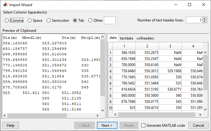
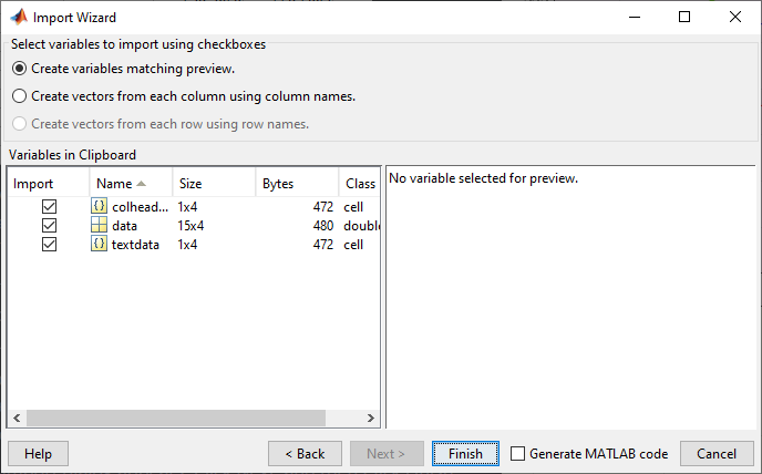
Note: If data does not meet requirements, process will abort.
This will include the data to the workspace, and also show the newly inlcluded data on the profile view.

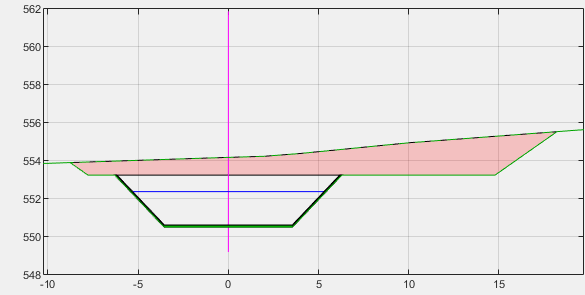
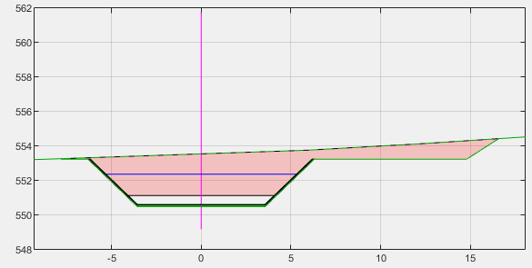
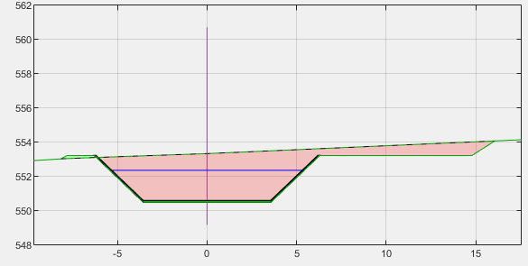
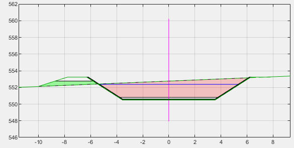
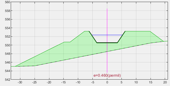
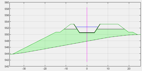
Cross-section at different stations can now be explored to show how executed work is captured and presented in BoQ documents.
Cross-section near 0+635
Cross-Section near 0+690
Cross-section near 0+725
Cross Section near 0+760
Cross-section near 0+805
Cross-section near 0+845
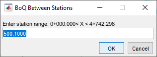
BoQ containing executed work volumes can not be generated, using the usual tool from Workflow > Table Data > Generate Route BoQ. Make sure to select any canal segment in the route, and insert the stations of interest.
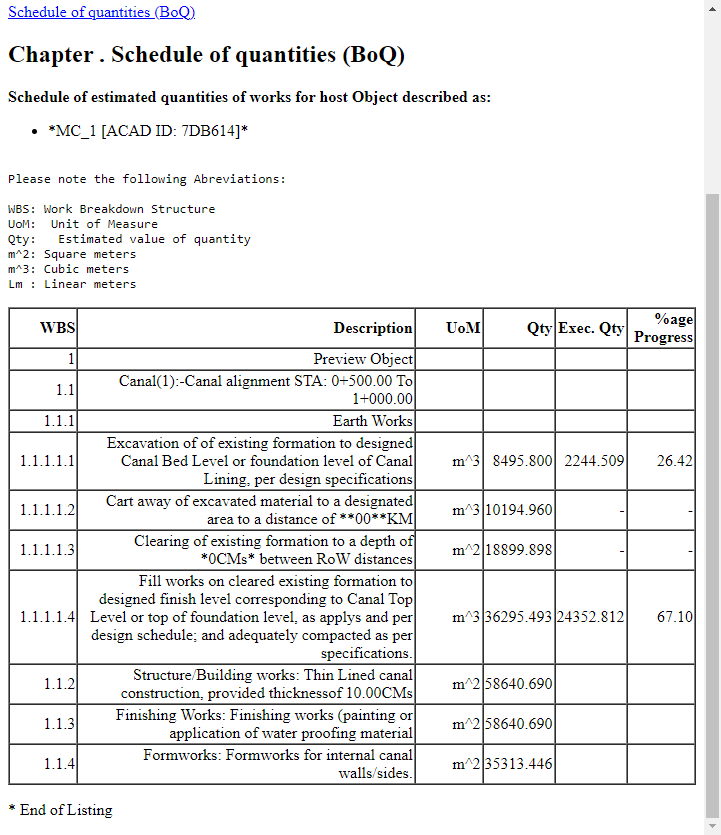
This will generate a listing similar to the figure below. It automatically includes earth work and fill information, and estimate percentage as a function of the design quantity available in the design information.
END.