CanalNetworkDocs_online
DrainNET Docs
Well Come to this section of documentation on the DrainNET product. It will provide you the basics of the product, it application and use cases as applies to the design and documentation of drainage canal network products. The product operates mostly on learnings and skills from using the CanalNET product. This page and its linked contents provide specific guidance on use cases and skills that are specific for use and application and drainage canal networks.
Important Notice The product is under testing and enhancement. Some of the informaiton contained in this page might change frequently, so stay tuned.
Use the below links to navigate the page and its contents.
Table of Contents
- Introduction
- Starting the Application
- The Interface
- Network Establishment and Resolution
- Project Preferneces
- Design Criteria for DrainNETWORK
- Naming Criteria
- Longitudinal Design of Drain Routes
- Working with Controls (Segments)
- Longitudinal design of segments
- Exploring Design
- Production of Drain Routes Design
- Using Dummy Routes
Introduction
DrainNET product is a software solution built on the robust alogirhms of CanalNET, but with specific resources for working with a network of drainage canals. This has helped in maintaining a set of standard workflows and conventions for the development task. It is also beneficial to the users, as key concepts covered while using CanalNET are largely applicable here as well. You may notice, that the size of this guiding material is small compared to some of our other documentiaons, and this is exactly the reason.
The key working knowledges regading the following are still applicable, and this document assumes the reader has sufficient practical knowledge of those concepts. What is provided here focuses on new topics and materials needed to use the product.
- Networks and their resolutoin
- Design criteria
- Working with controls and segments
- Longitudinal design
- Exploring and producing designs
Lets begin by introducing the interface.
Starting the Application
The application should be normally started from the windows desktop area or the shortcuts in the start menu. If not avialble, follow below steps to make it quickly accessible.
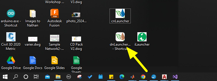
- Right click on the shortcut for CanalNET product and choose `Open File Location’.
- In the application folder, find the application file named dbLauncher.exe, and right click on it. Navigate to
Send to > Desktop (Create Shortcut).
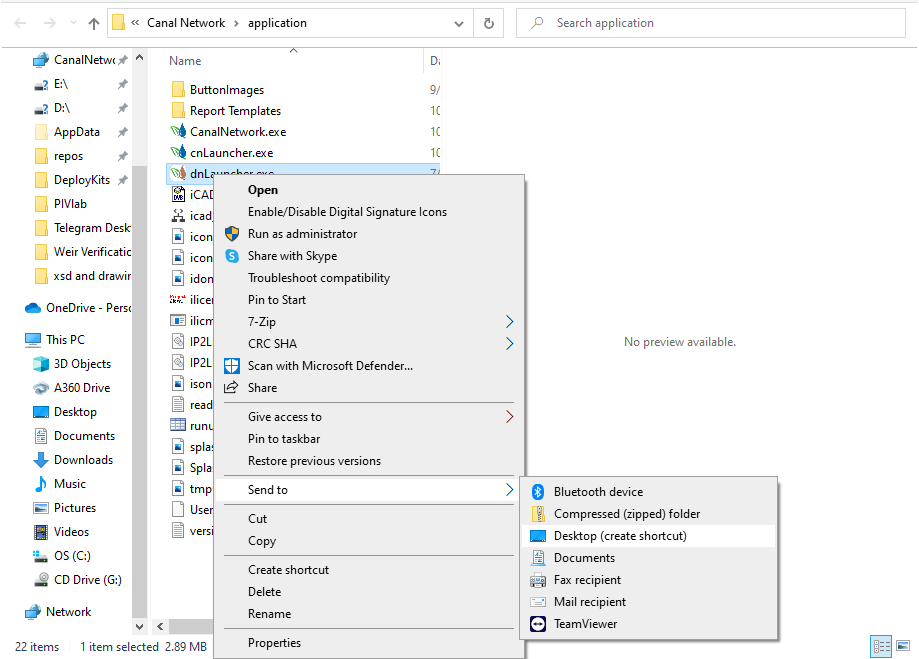
This will make the short cut avilable on your desktop, and the applciation can be started from it at any time.
The Interface
The latest version of DrainNET module looks as shown below. Notice the areas marked, highlighting key differences to expect from the CanalNET interface.
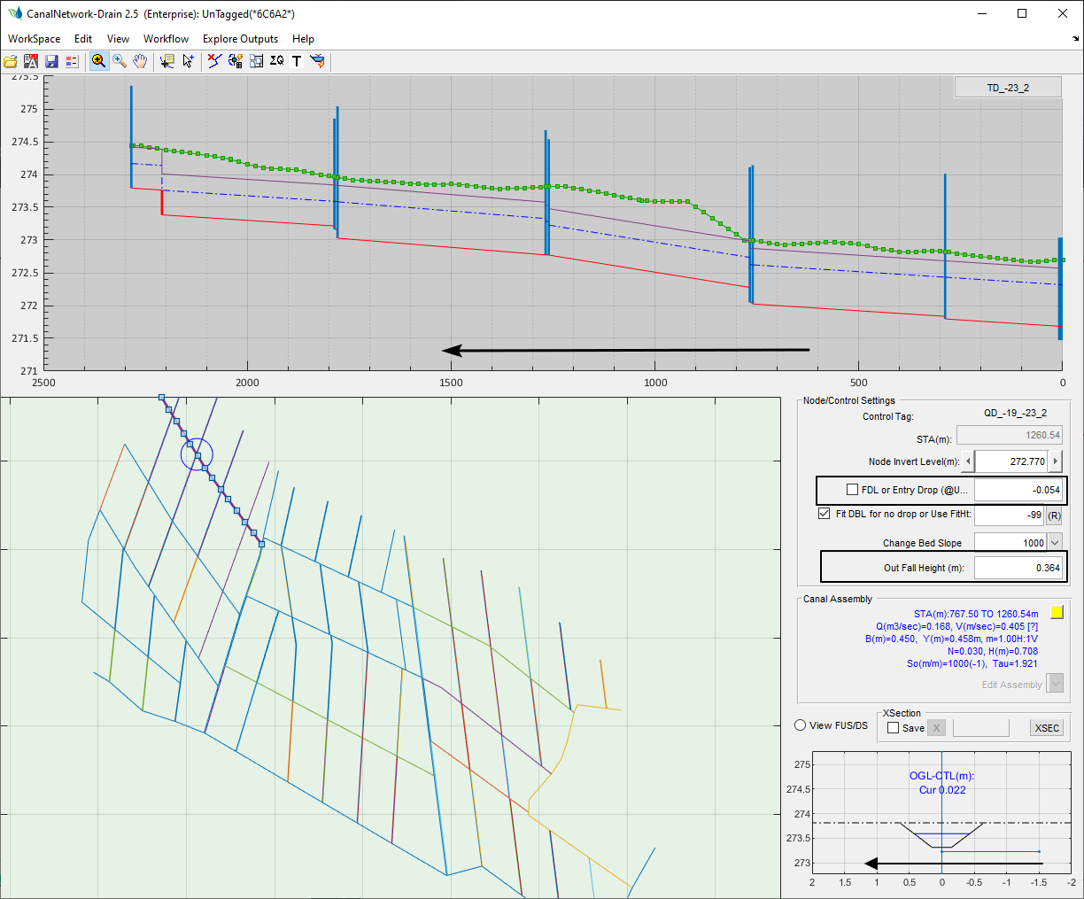
The differences are discussed below.
-
The prfile view axis The station in the profile view axis is presented as increasing from left to right. In contrast, CanalNET presents from right to left (normally). However, note that the flow direction is still from left to right (as in CanalNET.)
-
Similarly, the x axis markers on the detail view axis (bottom right) are also presented from left to right. Notice here, that the detail view for the FSL is positioned in the right direction (in accordance with the flow direction in profile view.) These are discussed more below on the topic of ‘Working with Controls’.
-
The
Node/Control Settingspanel contains few changes. The Entry drop is a modified version of Exit Drop in CanalNET. The Outfall height text box is a new information needed in drainage design.
That is all you need to know interms of the differences to the main interface.
Note: The CanalSection Designer tool is temporarily disabled, as there seems to be no much use for it. This may change in the future.
### General Assumptions and Conventions Back to ToC
Before we go in to more technical detail, lets cover key assumptions and conventions applied in the software.
-
Alignments are drawn away from their collector canals.
This convention is similar to that used in CanalNET. All canals have their starting point at the connection with the collector canal, and progresses away from it.
-
Nodes represent canal and flow conditions downstream.
This is similar to the convention is CanalNET. Each control, when clicked, will display properties representing the segment located downstream of the control. The changes made to the properties will also affect the same segment.
-
All juncitons are treated as outfall structures by default.
-
Dumy Routes used as needed. Networks for drainage canals are often small in size, feeding to a natural drain close by. This will require creating multiple networks of canals to fully model the entire system. While this is possible, multiple host objects need to be prepared and working with large number of small networks is really challenging. Dummy routes are introduced to tackle this challenge. The user can conect all small networks using a dummy route, and work on the entire irrigation field in one session.
Dummy routes are not designed, or included in any produciton output. See more further below on the topic ‘Using Dummy Routes’.
-
Finally, a design approach. DrainNET manipulates control inverts and canal bed levels to achieve feasible designs. It automatically assigns control invert levels by observing conditions to allow water flow. Any change to inverts (user initiated, or automatic process) will ensure water flows. This will be more clear on the topic ‘Longitudinal Designs’.
Network Establishment and Resolution
Initial definition of canal network data for use in DrainNET follows strict pre-processing workflow to make sure the network creatd is usable with little or no issues. The common preprocessing tasks are:
- Node Identification, and processing
- Naming

Once these are succesfully done, the remaining work is mostly automated.
Important Note: All the steps and guidelines presented in CanalNET are applicable here. The only difference is in the design criteria set.
Project Preferneces
The project preferences available are shown below. Notice the two key changes in this case, mnamely:
- Main Collector Exit Invert: This defines the exit level desired at the begining of the main collector drain. As is customary, this is input in one of two ways.
- A value between +5 and -5 to indicate relative to the OGL at exit location
- A positive value (>5) to indicate an absolute elevation value.
-
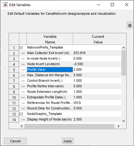
Profile View: This parameter determines the mode of profile view display. The following options are avilable.
- 0: Normal: Not applicable
- 1: Production Mode - used when producing designs to AutoCAD or documents. This will ensure published products include profile views with increasing station from left to right (end to begining)
- 2: Drain US Control - this view is needed during longitudinal design process.
** Important Tip** Make sure to keep the mode 2 enabled always, and change to mode 1 only whn you need to publish deisgn products.
<img src="./Images/Image 11.png">
Design Criteria for DrainNETWORK
Design criteria is a foundational input the canal network processing. Similar to CanalNET, DrainNET product uses a set of criteria to guide the design process in canals depending on their purpose and expected operating conditions. These are outlined and presented below.
Note: The criteria set are a subset of those used in CanalNET. As such it is expected that you will be familiar with all of them. We encourage you to re-visit the materials if needed here on this link.

The list of crieteria parameters are relatively small. You may notice missing criteria such as:
- Canal top provission
- Many command level crtieria (such as FSL-OGL)
Notice: This may change in the future.
The following table shows the default criteia set as used in different generations of canals in DrainNET.
[ToDO]
Naming Criteria
The naming crieteria for drainag networks is set from ‘Workspace > Manage Design Criteria > New Naming…` menu command. The commands brings up the following dialog.

The largest generation available is siz generations involving the following which also allows the use of dummy routes.
- PD
- MD
- SD
- TD
- FD
- QD
Note: Although the
Level II Desc. Textoption is available, it is not recommended to use it unless the impact on naming is the desired one. This may be removed in future releases.
Longitudinal Design of Drain Routes
This section covers the key elements of a longitudinal design process for a drainage route. Highlights are also made for key changes compared to use cases in CanalNET product, as this may tend to confuse begineer users.
Identifying Profile Views
As outlined above (in Project Preferences), ALWAYS keep mode 2 profile view on during design. You can identify which mode the current display is by looking at the direction of increasing stations on the profile view axis. If increasing from left to right, you are using the right mode.
If any of the elements (Controls, Segments) are not responding to clicks on the profile view axis, then the current view is in mode 1 (Prodiction mode.)
Working with Controls (Inverts)
Controls on the profile view axis represent junction nodes. And junctions in drainage networks represent Outfall structures. Their properties and behaviours must be understood in that perspective.
During Automatic design the following are considered.
- When ever possible, canal top levels start at OGL on the farthers feeder canals. This ensures avoiding cut work deliberately.
- Canal invert levels are fixed maintaining the minimum driving head from FDL of feeder canals, if any.
- In addition, controls influence hydraulic and geometric settings downstream of their location (until the next node).
The following schematic explains definitions and meaning of terms used, and governing principles for automatic design.
The invert level at a control is the minimum of:
- Max bed level due to invert and slope of preceeding control
- Max bed level needed by the feeder canal (including driving head)
- Max bed level needed to avoid backwater to upstream (FDL@entry>=FDL@exit)

[ToDO] Figure Key Terms and Definitions
-
Editing Inverts
Inverts can be adjusted lowered or hightnered as needed. However, the above conditions apply. To change invert levels, simply input the value on the eidt box.
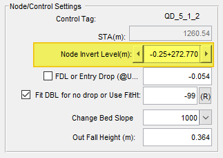
Tip You can input basic arithmatics on the Node Invert edit box, and the tool will calculate it. For istance to lower the current invert by 0.25m, just type -0.25+ before the currently displayed level. This will adjust the invert level as needed.
-
Entry Drops Entry drops compensate needed elevation differences in FSL either from upstream flow or from feeder canal flows. Inser a -ve value to prescribe a desired inlet level.
-
Fit for No Drop
Use this check box to avoid drops in the bed level design downstream of the node.

Release it to allow drops to be inserted.

Notice the changes on the DBL of the selected node in the drawings above.
-
Change Bed Slope
Input a desired bed slope value, or choose from the drop down menu to change bed level designs according to OGL variation or other hydraulic requirements.
-
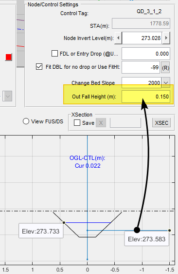
Outfall Height
This text box is a simple display box showing available fall height (between full drain levels) of feeder and collector canal at the control location.
Working with Controls (Segments)
Nodes represent segments downstream of them. Properties of segments that can be adjusted using the Node/Control edit panel tools are contained in the assembly Editor panel.
- Hydraulic Design
- Construction Variables
- CBL Design Settings
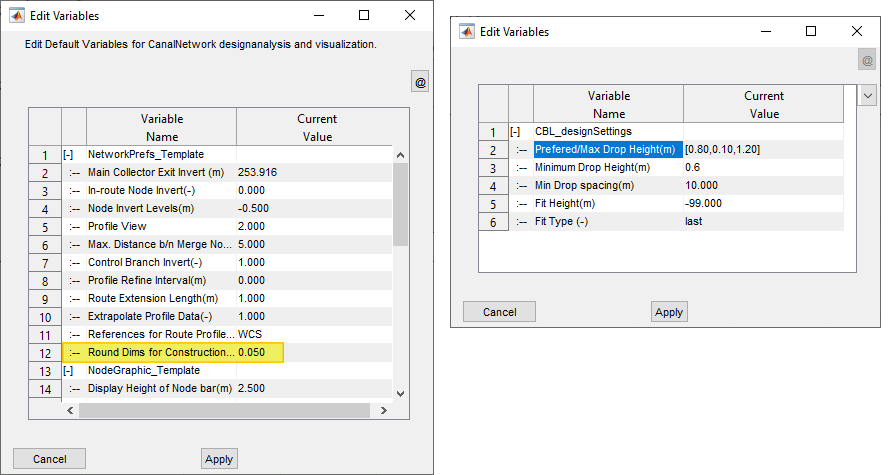
These can be used to override values set by the design criteria, and create a site specfic design as may be required by the location specifics. Among these the design of drops is essential to understand better.
- Design of Drops is influenced by the CBL_designSettings criteria set applied to each segment. The following criteria are at play on any segment.
-
If rounding is enabled, drop heights are rounded to multiples of the given value, and residual heights are compensated by RAISING the invert level of the downstream node.
-
If not, drops are calcualted per settings, and provided with out affecting the invert levels of the controls.
Note: This feature is yet to be integrated.
Figure: Describing values
Longitudinal design of segments
Design of routes is carried out by deciding the bed level information for the drain canal routes. This can be achieved mainly by using the Node/Control edit panel tools.
-
Make sure the profile view mode is set to 2(Drain US Control).
-
Click on the desired route in the layout view to display the longitudinal profile of the route, along with all involved structures. A tentative design is presetned using the design criteria settings
The invert levels for each node are worked out to meet all of the following criteria:
- Bedslope from upstream node
- feeder route FSL (if any)
- NodeIvert value set in Project preferences.
-
Click on a control, and use the tools on the Node/Control Panel.
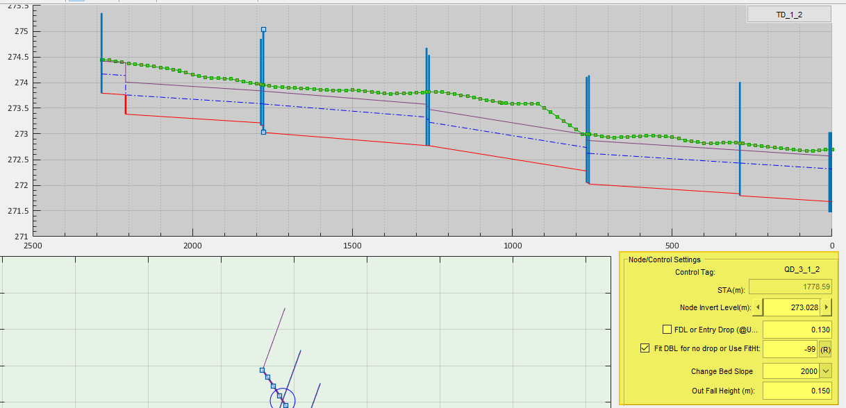
Any changes to the node edit panel tools, will ensure designs are consistent with the above three requirements. For instance, you can not raise invert levels beyond a certain limit with out failing to meet all of them.
Note: In DrainNET, all nodes represent the segment downstream of them. Changing the slope of the node, changes the bed level of the segment located next to it.
- If drops are required, use the prefered, minimum and maximum heights as needed to provide well arranged drops.
-
Use the
Workflow > Data & Analysis > Release Inverts...menu command to release inverts, and start design afresh.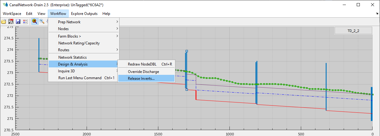
Note: To release a single node, select it in the profile view, and start the command. Choose
Continue.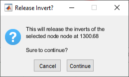
To release inverts of all nodes in a route, select the route in layout view and start the command. Choose
Remove All.
To release the invert of the node at the collector drain (for the current route), start the command and choose
Remove Collector.
Have a look at the example below for invert design considerations.
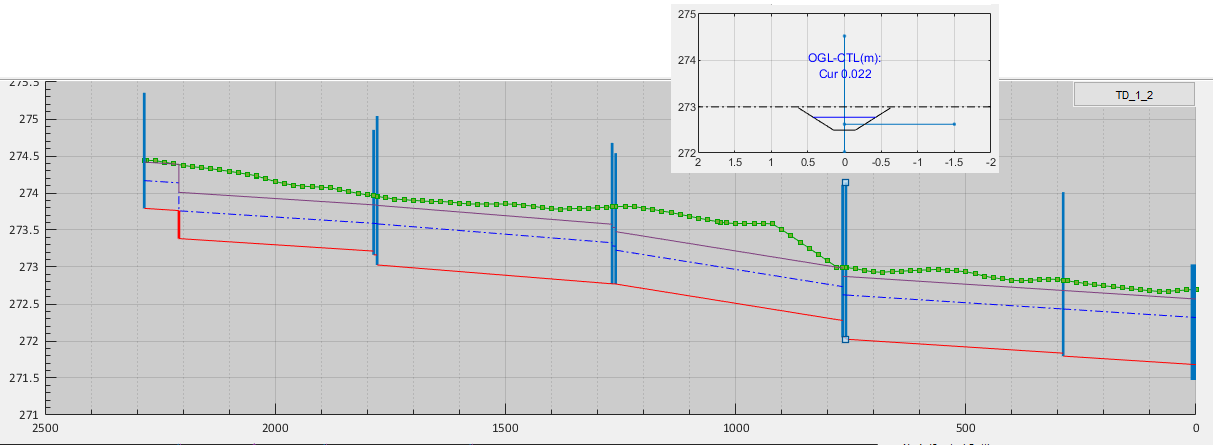
One may be tempted to raise the invert level of the 3rd node (from begining). However, this is impossible. Infact, it is a well designed situation. Because, as you can see in the clipped image right above it, the feeding drain canal fully uses the allowed driving head and no more space for further invert adjustment.
Recommended Practice: To avoid back and forth in design, we recommend:
- to start with the last generation (farthest) feeder canals and design them before continuing.
- Continue with the next generation canal (collector canals).
- Progress toward the primary generation canal (main collector drain).
Exploring Design
Note: Exploring results for production gives station values corresponding to production view, and must be applied. In design view, the regular prestnetaion style (increasing station from left to right) is used.
Annotations
Annotations are accessed from Explore Outeputs > Annotations... menu command.
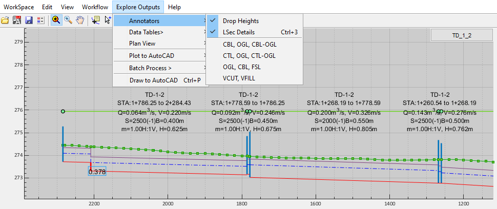
Cut/Fill work visualization
Start the menu command `Explore Outputs > Annotations > VCUT/VFILL and an interactive guide will apear.
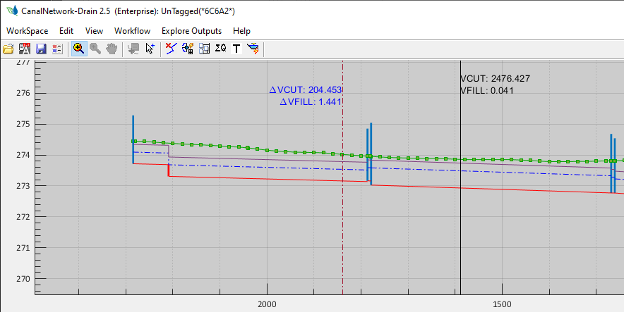
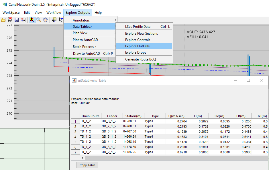
Table Data for Outfalls
Explore dimesnion tables for all outfall structures in a selected route ftom the menu command.
Note, the Outfall structures are designed as per EEC internal standards. The typical drawings are attached below for reference.
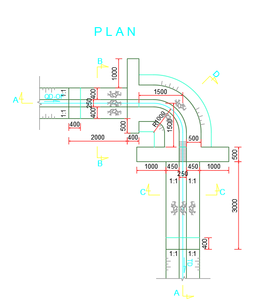
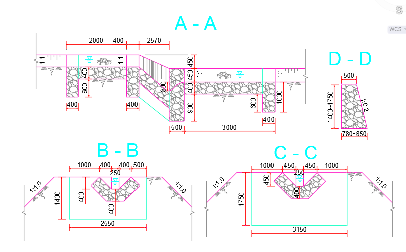
Figure: Showing Outfall Type I details.
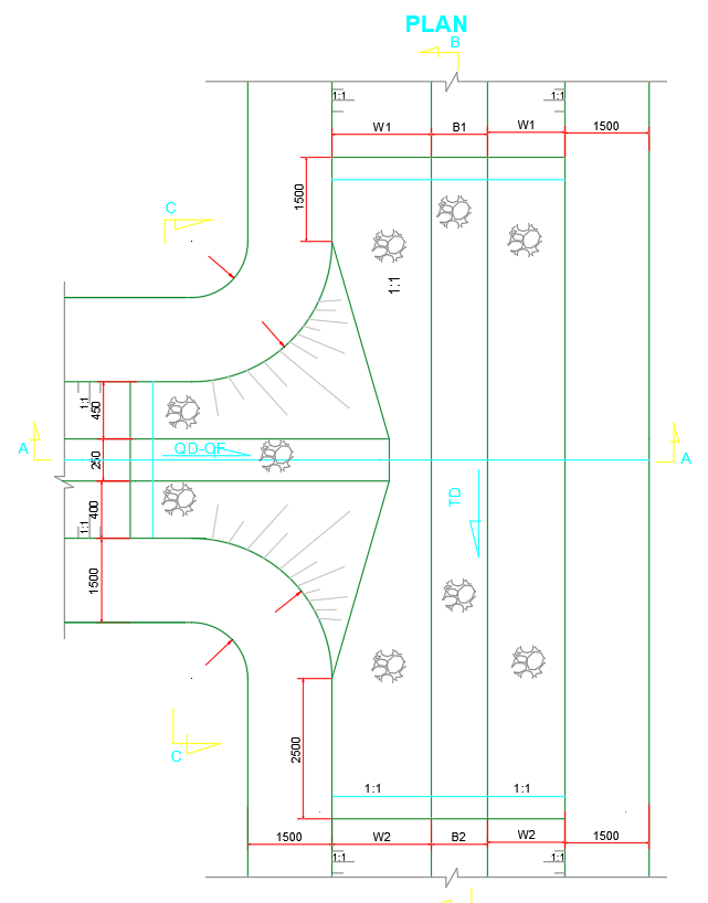
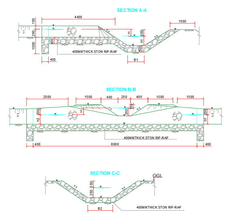
Figure: Showing Outfall Type II details.
Generate BoQ
Generate for a selected route from the menu command.

Production of Drain Routes Design
For production tasks the view mode must be returned to 1 (in project preferences.) This will ensure, stations in all products are created in accordance with common convention. See screen shot of preferences below.

Generating LSec Products
Generate Lsec Drawing from Workflow > Plot To AutoCAD > Plot LSec menu command.

Generate Outfall Structure Drawings
Generate drain related structures from the workflow menu, and choose the desired drawing.
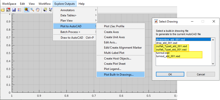
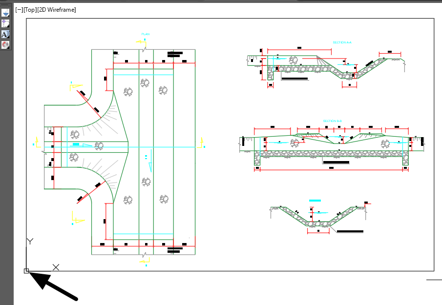
AutoCAD will be in selection mode ready to accept input. Point to the deisred location of importing the drawing, and the contents will be generated.
Note: The insertion point is used as the bottom left corner of the generation area.
Using Dummy Routes
[To Be Completed]